
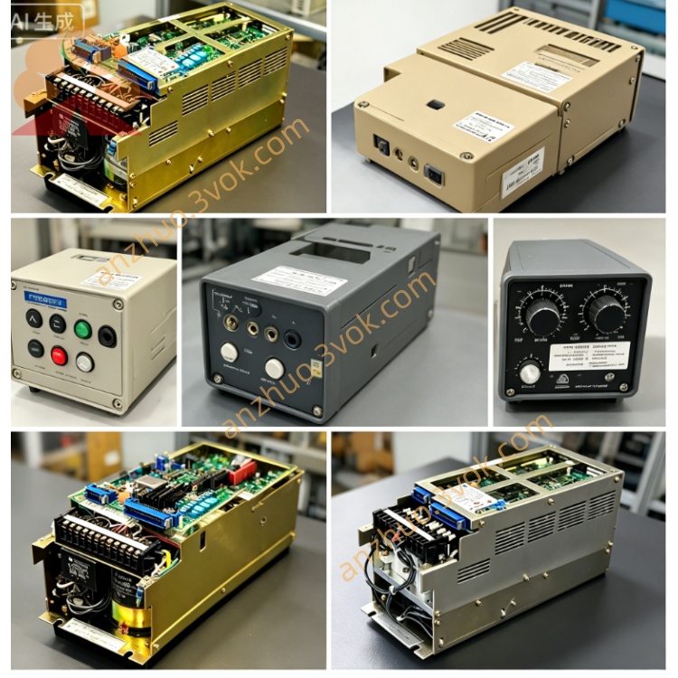
YASKAWA JANCD-SP20C dedicated axis control board
JANCD-SP20C is a dedicated axis control board manufactured by Yaskawa Electric, specially matched with Yaskawa CNC series control systems, belonging to the servo drive control unit inside the numerical control cabinet. This board undertakes the core signal transmission and motion closed-loop control between the CNC main controller and servo drive units, serving as the key intermediate hardware for coordinating multi-axis linkage, spindle speed regulation and position feedback processing. It adopts industrial-grade anti-interference circuit design, complies with international industrial electrical standards, and is widely used in medium and small-sized machining equipment equipped with Yaskawa CNC systems. The overall structure is compact, designed for built-in cabinet installation, with stable long-term continuous operation performance under factory workshop temperature and electromagnetic interference environment.
Description
Product Introduction
JANCD-SP20C is a dedicated axis control board manufactured by Yaskawa Electric, specially matched with Yaskawa CNC series control systems, belonging to the servo drive control unit inside the numerical control cabinet. This board undertakes the core signal transmission and motion closed-loop control between the CNC main controller and servo drive units, serving as the key intermediate hardware for coordinating multi-axis linkage, spindle speed regulation and position feedback processing. It adopts industrial-grade anti-interference circuit design, complies with international industrial electrical standards, and is widely used in medium and small-sized machining equipment equipped with Yaskawa CNC systems. The overall structure is compact, designed for built-in cabinet installation, with stable long-term continuous operation performance under factory workshop temperature and electromagnetic interference environment.
Model Definition Explanation
JANCD: Unified prefix of Yaskawa CNC series internal control circuit boards, representing CNC dedicated printed circuit board hardware platform;
SP: Functional classification code, SP stands for Spindle & Servo Control Board, indicating the board integrates spindle signal processing and servo axis control dual functions;
20: Hardware version and performance grade code, representing the second-generation medium-load control specification, supporting standard multi-axis synchronous control logic;
C: Revision version suffix, representing the third optimized circuit revision, upgraded in anti-interference circuit layout and signal transmission stability compared with earlier A and B versions.
Technical Specifications
The working input voltage of the board is DC 24V, with allowable voltage fluctuation range from DC 21.6V to DC 26.4V. The internal logic circuit operating current is controlled within 1.2A under full-load running state. The operating temperature range for normal operation is 0 to 55 degrees Celsius, storage temperature range is minus 20 degrees to 70 degrees Celsius, relative humidity requirement is 5% to 90% without condensation. It can withstand vibration intensity of 0.5G within frequency band 10 to 55Hz during equipment operation. The position signal processing response delay is less than 0.8 microseconds, supporting high-speed pulse signal acquisition up to 4MHz frequency. The board supports up to 6 servo axes simultaneous closed-loop feedback processing and single spindle analog speed signal output. The insulation resistance between internal power circuit and signal circuit exceeds 100 megohms, with surge and short-circuit protection circuits built into each signal channel. The service design life under rated working environment reaches 80,000 hours of continuous operation.
Interface and Communication Configuration
This control board is equipped with multiple types of terminal interfaces and dedicated bus connectors. Servo signal connectors are used for bidirectional transmission of position feedback signals, speed command pulses and servo alarm signals between the board and each servo driver. Spindle analog output interface outputs 0 to 10V analog voltage signals to adjust spindle operating speed, with independent enable and fault feedback signal pins matched. Digital input terminals receive external limit switch, reference point detection, emergency stop and machine tool auxiliary locking switch signals. Digital output terminals send spindle operation enable, servo ready, axis in-position completion and fault alarm output signals to peripheral relay modules. The internal backplane communication interface adopts Yaskawa proprietary parallel bus protocol to realize high-speed data exchange with CNC main board, transmitting axis position commands, parameter data and real-time operating state information without additional external communication wiring. All signal interfaces adopt shielding wiring design to restrain electromagnetic signal crosstalk, and each external signal channel is equipped with independent fuse protection circuit to avoid single-channel short-circuit damaging the whole board.
Core Functions
First, multi-axis closed-loop motion control function: receive position commands issued by CNC main unit, convert digital commands into servo drive control signals, collect real-time position encoder feedback signals of each axis, form closed-loop adjustment to ensure positioning accuracy and repeated positioning precision of linear and rotary axes. Second, spindle signal centralized processing function: output analog speed regulation signals, collect spindle position and rotation speed feedback signals, realize spindle orientation, constant surface speed control and spindle fault signal detection. Third, machine tool peripheral signal logic processing: detect all travel limit, origin switch and safety interlock signals of the machine tool, feed back abnormal trigger signals to the CNC system in real time, and output execution signals for auxiliary actions such as spindle startup and axis locking. Fourth, real-time fault diagnosis and upload function: monitor abnormal states including servo overcurrent, signal disconnection, short circuit and overvoltage of each channel, store fault code information locally and transmit fault data to the human-machine operation panel for display. Fifth, parameter storage and operation matching function: store axis gain, acceleration and deceleration parameters, spindle control parameters and machine tool mechanical compensation parameters on the board, automatically call corresponding parameter groups during equipment startup to match different processing motion requirements. Sixth, anti-interference signal filtering function: built-in hardware filter circuit filters high-frequency clutter interference of pulse and analog signals, effectively reducing position drift and motion jitter during high-speed cutting.
Applicable Scenarios
The board is mainly supporting hardware for all kinds of numerical control machining equipment equipped with Yaskawa standard CNC systems. It applies to vertical machining centers, horizontal milling machines, CNC lathes and compound turning-milling machines with 3 to 6 linkage axes in metal cutting industry. It can be matched with small precision grinding machines, tapping machines and engraving milling equipment in mold processing workshop. It is suitable for automatic feeding numerical control equipment in automotive parts processing production lines, stamping and post-processing CNC machine tools. It also adapts to small-scale customized processing equipment in hardware manufacturing, electronic part precision cutting machine tools, and semi-automatic numerical control processing equipment with independent spindle unit. It can work stably in general factory production workshop environment with dust, slight oil mist and normal electromagnetic interference, and is not suitable for corrosive gas, strong conductive dust and continuous high humidity unventilated environment without protective cabinet.
Operation and Maintenance Instructions
Operation Instructions
Before powering on the equipment, check that all connectors of JANCD-SP20C are fully locked without loose wiring, confirm no metal debris or oil dirt remains on the surface of the circuit board. After DC 24V power supply is connected, wait 30 seconds for the board to complete self-inspection; abnormal alarm codes displayed on the operation panel indicate interface disconnection or circuit fault of the board, and power supply must be cut off for inspection immediately. During equipment high-speed operation, do not touch the board or pull any signal connectors randomly, avoid strong impact on the control cabinet where the board is installed. When switching processing programs with different axis speeds and loads, do not exceed the maximum supported axis number and signal frequency range of the board to prevent signal overload triggering protection shutdown. When long-term shutdown is required, cut off the total power supply of the CNC cabinet instead of only turning off the operation panel power to avoid long-term low-voltage standby aging of the board circuit components.
Maintenance Instructions
Conduct routine inspection every three months: cut off the cabinet power and wait for more than 10 minutes for internal capacitance discharge, use dry compressed air with low air pressure to blow off dust accumulated on the surface of the circuit board, do not use liquid cleaning agent to wipe the board body. Check whether each terminal wire has aging, oxidation and loose pins, polish oxidized contact points with fine sandpaper and re-fix wiring. Every one year, check the internal fuse of each signal channel of the board, replace fuses with same specification if blown, and prohibit using fuses with higher current specification instead. If the board frequently reports signal disconnection fault, check the shielding layer damage of matching signal cables first, and replace aging cables. When the board has persistent unrepairable fault such as circuit burnout, replace the whole board instead of disassembling and welding internal small components without professional maintenance equipment. Storage of spare boards requires placing them in anti-static packaging bags, storing in dry and constant temperature environment, avoiding direct sunlight and heavy extrusion. When installing a replacement board, wear anti-static wrist strap connected to cabinet ground wire to prevent static electricity from breaking down integrated chips on the board. Regularly export and back up axis and spindle parameters stored on the board to the CNC system storage device, avoiding parameter loss after board replacement affecting equipment normal operation.
Get a Quote