
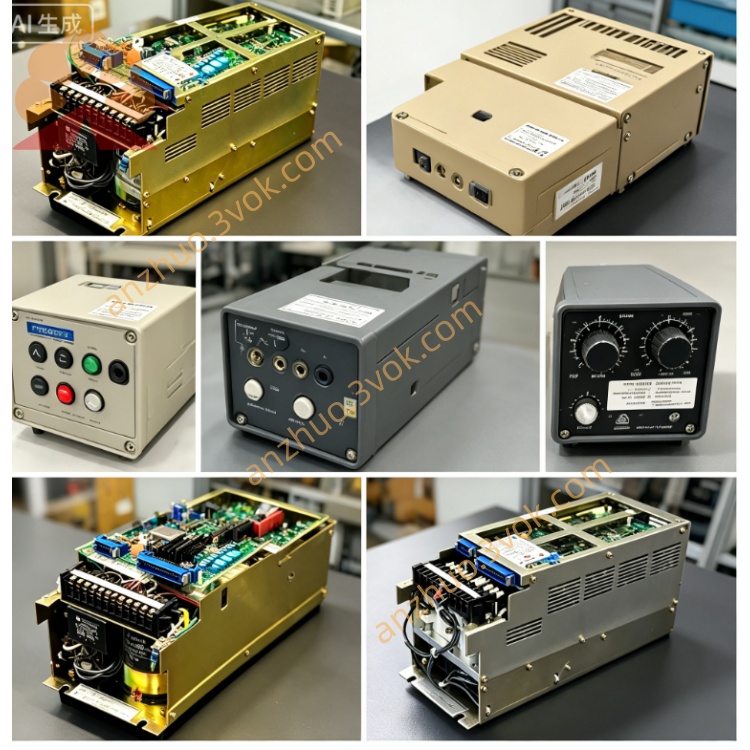
YASKAWA JASP-WRCA01 original Yaskawa Motoman SERVOPACK main servo control PCB board
Description
1. Product Overview
2. Core Functional Description
2.1 Servo Motion Control Function
2.2 Auxiliary Control Logic
3. Electrical Parameter Specification
3.1 Power Input
+5V: Rated output 5A for core logic circuit
+7V: Rated output 2.5A for drive pre-drive circuit
+15V: 1.3A; -15V:0.6A for analog signal & encoder circuit
Front-end single-phase AC input of matched power supply: AC200~220V (+10%/-15%, AC170V~242V), 50/60Hz(48~62Hz).
3. Power Consumption & Physical Size
Rated overall power consumption: approx 22W; PCB dimension:150mm(L)×100mm(W), total net weight:0.45kg
All encoder signal adopts differential transmission with built-in surge suppression circuit to resist welding workshop high-frequency electromagnetic interference.
4. Environmental Working Conditions
Continuous operating ambient temperature: 0℃ ~ +55℃ inside closed servo cabinet
Storage temperature range: -25℃ ~ +70℃; non-operating extreme storage: -55℃~+125℃
Relative humidity:30%~80%RH, no condensation allowed; Protection grade IP20 (only install inside sealed SERVOPACK housing)
Max applicable altitude ≤1000m without power derating; anti-vibration level ≤0.5G for production line vibration environment; forbidden to mount at site with corrosive gas, conductive metal dust and welding spatter.
5. Connector & LED Indicator Definition
5.1 Wiring Interface
Backplane gold finger socket: plug into internal SERVOPACK backplane to obtain multi-group DC working power and internal bus communication with converter/amplifier modules;
External terminal connectors: multi-channel encoder feedback terminals for six-axis motor cable connection, one group interlock signal terminal connecting to JANCD-XTU01 contactor board; reserved factory calibration pin header unused under normal operation.
5.2 Onboard LED Status
PWR(Green): Steady ON = +5V main logic power normal; OFF = control power supply failure or onboard fuse blown;
RUN(Green): Periodic flashing = MCU system running normally and bus communication ok with main CPU; always OFF = core firmware damage or hardware breakdown;
ERR(Red): Steady ON = serious servo fault (overcurrent, encoder open, converter abnormal); intermittent flash = transient wiring interference or momentary safety trigger;
AX-Yellow: Corresponding lamp flickers when matched axis motor runs; OFF = channel cable break or amplifier power loss.
6. Installation & Replacement Operation Guide
Cut off total cabinet AC input power before disassembly; wait ≥20min for high-voltage capacitor full discharge inside SERVOPACK to avoid residual voltage component damage;
Unfix SERVOPACK housing screws, pull out old control board horizontally after disconnecting all external terminal cables; clean backplane socket dust with anhydrous alcohol;
Align new JASP-WRCA01 gold finger with backplane slot and insert fully, lock fixed buckle, reconnect all encoder and interlock wiring in original definition;
Power on cabinet after assembly, enter robot teach mode to execute servo axis origin calibration one by one before trial running.
7. Common Fault Troubleshooting
All PWR lamp off: Check JUSP-RCP01AAB control power AC input voltage and onboard protection fuse of WRCA01 board; replace blown fuse with same specification;
Normal power but RUN always off: Clean gold finger oxidation dirt; replace board if fault persists;
Single axis ERR lamp constant lighting: First inspect corresponding motor encoder cable open/short; replace WRCA01 board channel when peripheral wiring is intact;
Random intermittent ERR flicker: Check servo cabinet internal damp or loose wiring terminal.
Get a Quote