
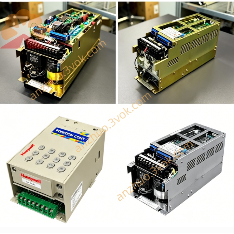
YASKAWA YPHT31600 original main control CPU board
YPHT31600 is the original main control CPU board manufactured by Yaskawa, specially matched with A1000 series frequency inverter; common suffix versions include YPHT31600-1D and YPHT31600-1E, corresponding to different power-section specifications of A1000 drive series. It is the core motherboard responsible for operation logic calculation, signal receiving, parameter storage and drive closed-loop control of the inverter, widely used for maintenance replacement of damaged A1000 inverters in industrial automation equipment.
Description
Product Introduction
YPHT31600 is a high-performance AC servo drive independently developed for high-precision motion control demands. It adopts advanced vector control algorithm and high-speed current loop processing architecture, featuring compact integrated design, strong overload capacity and stable operation under complex load conditions. The product is compatible with matched medium-power servo motors, delivering fast response speed, low torque fluctuation and high positioning accuracy, widely used in automated production equipment to realize stable speed, position and torque closed-loop control. The whole machine supports multi-mode switching control, with built-in anti-interference circuit to adapt to harsh industrial electromagnetic environments, and reserved abundant expansion functions for flexible secondary development.
Model Definition
YPHT stands for the series code of high-power general servo drive; the digital segment 31600 represents rated matching power specification of 16kW. The coding rule distinguishes product series, power grade and hardware configuration, facilitating model selection, inventory management and after-sales maintenance. No additional suffix indicates standard hardware version; customized functional modules will be marked with extended suffixes separately.
Technical Parameters
The rated input voltage range is three-phase 380V alternating current, allowable voltage fluctuation range covering minus fifteen percent to plus ten percent of rated value. Rated output power reaches 16 kilowatts, continuous rated output current is 32 amperes, peak overload current supports three times rated current lasting for sixty seconds. The built-in main control chip supports position loop response bandwidth up to 2 kilohertz, speed loop bandwidth up to 1.2 kilohertz. Position control resolution supports multi-level electronic gear ratio setting, maximum electronic gear ratio range from 1 to 65535. Operating ambient temperature ranges from zero degree Celsius to forty-five degree Celsius; storage temperature ranges from minus twenty degree Celsius to seventy degree Celsius. Protection grade of the main body is IP20, applicable for indoor cabinet installation. Overall weight is about 12.8 kilograms, main cooling mode is forced air cooling with built-in cooling fan. The internal bus voltage withstand capacity and power device insulation performance meet international industrial electrical safety standards.
Interface and Communication Configuration
Digital signal interfaces include multi-channel digital input terminals for external enable, fault reset, origin signal and multi-stage speed switching; multi-channel digital output terminals for fault alarm, operation status and positioning completion signal feedback. Analog signal interfaces contain two groups of analog voltage input channels for torque and speed analog command input, one group analog output channel for real-time speed or torque monitoring signal output. Encoder interface supports differential line driver encoder signal receiving, compatible with 2500 line incremental encoders and multi-bit absolute encoders. Standard communication interfaces include Modbus RTU serial communication port for upper computer parameter reading and writing, and reserved EtherCAT industrial bus communication interface for high-speed synchronous linkage control of multi-axis equipment. Power interfaces cover three-phase main power input terminal, servo motor power output terminal and independent braking resistor external connection terminal. Separate control power supply interface is configured to ensure signal circuit normal power supply during main power failure.
Core Functions
Three control modes are integrated, including position closed-loop control, speed closed-loop control and torque closed-loop control, which can be switched freely through parameter setting. Built-in automatic motor parameter identification function can complete stator resistance, inductance and encoder offset detection with one click without manual calibration. It supports electronic cam and multi-segment position curve interpolation operation, realizing fixed reciprocating motion and segmented positioning logic without external controller programming. Built-in complete fault diagnosis logic, capable of real-time detection of overcurrent, overvoltage, undervoltage, overload, overheating, encoder abnormal and wiring error faults, with fault code storage and historical fault record query function. Vibration suppression filter and notch filter functions are embedded to eliminate mechanical resonance during high-speed operation, improving motion smoothness. Quick stop and soft stop logic can be configured separately, matching different safety production requirements. Support electronic gear function for multi-axis synchronous transmission, and zero-speed full torque output to maintain static positioning rigidity.
Application Scenarios
Suitable for medium and heavy-load automated processing equipment, including numerical control cutting machine tools, metal stamping automation lines and large gantry handling robots. Widely applied in new energy battery production equipment such as pole piece rolling machines and automatic stacking machines. It can be used for packaging industry heavy-duty winding, slitting and cutting equipment, as well as textile printing and dyeing large roller transmission systems. Also applicable to logistics three-dimensional warehouse lifting and traversing servo axes, plastic injection molding manipulator positioning drive, and woodworking engraving large stroke motion platforms. It meets the high precision and high stability motion demands of medium-power industrial automation production lines with continuous long-time operation requirements.
Operation and Maintenance Instructions
Before power-on, check whether power wiring, motor wiring and encoder wiring are firmly connected, confirm no short circuit between power lines and ground, and verify the braking resistor specification matches the drive power grade. Complete motor parameter auto-tuning before formal operation, and adjust filter and gain parameters according to actual mechanical vibration condition. During daily operation, regularly observe the operation indicator light and real-time temperature data, avoid long-term continuous operation under full overload state. Maintain good ventilation of the installation cabinet, clear dust and foreign matters on the cooling fan and heat sink every one to three months according to the on-site dust environment. Cut off all power supply before disassembly and maintenance, wait for more than ten minutes for internal bus capacitor discharge to prevent electric shock risk. Do not disassemble the internal power module and main control board without authorization; damaged components shall be replaced with original matching accessories. Regularly back up drive parameter data to avoid parameter loss after fault reset. When fault alarm occurs, stop equipment operation immediately, check corresponding fault code and eliminate wiring, load or power supply abnormal causes before restarting. The service life of the built-in cooling fan is about twenty thousand hours, replace the fan in advance once abnormal noise or speed drop appears. Store the product in dry, dust-free and vibration-free environment when not in use for a long time, and power on for two hours every six months for moisture-proof maintenance.
Get a Quote