
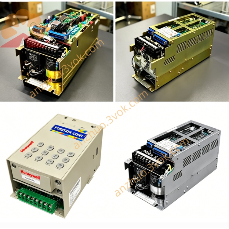
YASKAWA CACR-PR02AC4ER rack-mounted AC servo drive
Model CACR-PR02AC4ER is a rack-mounted AC servo drive of YASKAWA classic CACR-PR series with rated power of 0.2kW. It belongs to the early digital positioning servo unit matching M/F/S servo motor series, compatible with USAMED, USAFED and USASEM servo motors fitted with incremental encoders.
Description
1. Product Introduction
CACR-PR02AC4ER is a compact low-power analog AC servo drive under YASKAWA classic CACR-PR series, designed for small-load high-precision motion control. It adopts full closed-loop three-loop control architecture, matched with YASKAWA small inertia low-power AC servo motors. The unit integrates power drive, signal processing and protection circuits in a miniature housing, supporting analog voltage speed/torque commands and differential pulse position commands. It features fast dynamic response, low speed ripple, strong anti-interference and low heat generation, suitable for compact automated machinery with limited installation space. The built-in standard brake circuit eliminates extra braking units for light cyclic loads, and reinforced shielding suppresses electromagnetic interference in dense wiring cabinet environments.
2. Model Code Explanation
CACR: YASKAWA general AC servo driver series identifierPR: Analog control type, supporting ±10V analog speed and torque command input02: Rated matching motor power specification, corresponding to 0.2kW small servo motorA: Standard control circuit hardware version with default analog signal terminal layoutC: Equipped with internal integrated regenerative brake circuit for light load energy dissipation4: Encoder interface specification, compatible with 2500-line incremental differential encoderE: Enhanced EMC shielding structure for factory electromagnetic harsh environmentR: Global general industrial specification, supporting wide-range input voltage and standard international signal level
3. Technical Specifications
The drive is matched with 0.2kW rated servo motor. Main circuit three-phase input voltage ranges from AC 200V to 230V, allowable fluctuation ±10% of rated voltage. Control circuit uses independent single-phase AC 100V–240V power supply to isolate control signals from power circuit noise. Rated continuous output current is 1.8A, short-time peak output current reaches 5.4A for acceleration and deceleration. Supported motor maximum speed is 6000 rpm, speed adjustment ratio up to 1:10000, speed fluctuation rate below 0.03% under constant light load. Maximum input pulse frequency for position control reaches 500kHz, position loop response bandwidth adjustable between 100–1000Hz. Built-in regenerative brake resistor handles routine light braking energy; overcurrent protection triggers at 150% rated output current, overvoltage protection activates when DC bus exceeds 320V, undervoltage protection works below 170V DC bus. Operating ambient temperature 0°C to 55°C, storage temperature -20°C to 70°C, relative humidity 5%–90% without condensation. Vibration resistance reaches 0.5g within 10–200Hz frequency band, suitable for light vibration production equipment.
4. Interface and Communication Configuration
Control terminal block integrates complete analog, digital and pulse signal interfaces. Analog channels include ±10V speed command input, ±10V torque command input, independent analog speed and torque monitoring output for external signal collection. Digital input terminals support servo enable, forward/reverse rotation permission, alarm reset, zero clamp, gain switching and position deviation clear, compatible with NPN and PNP 24V open collector signals. Digital output terminals provide servo ready, positioning completion, speed reach, fault alarm and external brake drive signals to trigger external relays. Position pulse input supports three modes: differential line driver pulse, single-ended open collector pulse, A/B phase orthogonal pulse. A reserved RS232 serial port on the front panel serves as exclusive local debugging communication, used for parameter modification, real-time operation data reading and fault history query via dedicated YASKAWA software. No built-in industrial fieldbus interface; optional external communication modules are required for PROFIBUS or DeviceNet connection. Motor side has separate power cable connector and encoder feedback connector, the 4-code encoder channel receives differential 2500-line incremental encoder signals to resist wiring interference. All signal terminals reserve shielding grounding terminals to optimize EMC performance of the E suffix version.
5. Core Functions
Three independent closed-loop control loops (current, speed, position) with separately adjustable gain parameters to balance dynamic response and stationary stability. Electronic gear function allows arbitrary configuration of pulse count corresponding to one motor rotation, simplifying mechanical transmission matching without mechanical modification. Internal storage supports up to 16 groups of fixed position data, enabling automatic fixed-point motion triggered by external digital input signals without continuous pulse output from upper controllers. Electronic cam function generates continuous variable speed motion curves to replace traditional mechanical cams for repeated profiling work. Integrated full-range protection logic covers overcurrent, overvoltage, undervoltage, continuous overload, motor overheat, encoder wire break, main circuit fuse damage, control circuit abnormality and position deviation overflow; all fault codes are stored in non-volatile memory for post-failure inspection. One-click automatic load inertia tuning identifies actual mechanical inertia and optimizes loop gains automatically to avoid complex manual parameter debugging. Zero-speed holding torque function locks the motor shaft at standstill to prevent position drift under tiny external disturbance. Adjustable soft acceleration and deceleration curves limit torque mutation, reduce impact on small precision transmission parts such as tiny bearings and micro couplings. Multi-stage gain switching function switches high/low response gain via external signals to meet both fast moving and stable positioning demands.
6. Applicable Scenarios
This low-power analog servo drive targets compact small-load precision automation equipment with limited cabinet installation space. It fits electronic component sorting machines, small PCB dispensing equipment and desktop laser marking devices requiring micro-positioning and low-speed stable operation. It matches miniature packaging machinery including small labeling machines, desktop filling equipment and tiny carton folding mechanisms for short-stroke reciprocating positioning. It applies to textile fine winding equipment, small printing roller driving structures and laboratory precision test benches with light cyclic loads. It is widely used for upgrading old analog control small automation equipment, where original analog controllers are retained without full upper system replacement. It is suitable for desktop processing equipment, miniature manipulator single-axis drive and optical equipment focusing adjustment axes. It is not recommended for heavy inertia loads, high-frequency ultra-short cycle rapid reciprocating equipment or machinery with long-time large braking energy release.
7. Operation and Maintenance Instructions
Operation Guidelines
Complete full wiring inspection before power-on, check tight connection of main power cable, encoder cable and control signal wiring; confirm no short circuit between power terminals, and all shielding wires connect reliably to cabinet ground bus. After initial power-on, input matched motor rated power, rated current and encoder resolution parameters first, then run load auto-tuning under no-load state. Adjust speed and position loop gains step by step after tuning; excessive gain will trigger mechanical resonance and vibration of small transmission parts. Do not run the drive continuously beyond rated load and voltage range; reduce continuous running load when ambient temperature exceeds 45°C to avoid overload alarms. For long-time shutdown, cut off main circuit power supply first then control power supply; wait a minimum of 10 minutes for internal DC bus capacitors to fully discharge before disassembling wiring to prevent electric shock. Avoid frequent power on/off within 3 minutes, repeated rapid power cycling will damage internal power switching modules. Keep the ventilation channel of the heat sink unblocked and free of stacked wires blocking air flow.
Maintenance Instructions
Perform dust removal every 1–3 months based on on-site dust level; use low-pressure dry compressed air to blow dust from heat sinks and circuit boards, never wipe circuit components with liquid detergent or chemical cleaning agents. Inspect all terminal blocks and cable connectors every 6 months, retighten loose screws caused by long-term vibration; check power cable insulation for aging or cracking and replace damaged cables immediately. Check built-in cooling fan operation monthly; replace the fan once abnormal noise or stall occurs to prevent power module overheating burnout. Back up all parameter configurations through debugging software every 6 months to avoid total parameter loss after fault reset. Regularly test grounding wire continuity and grounding resistance to maintain EMC shielding performance and lower signal interference failure rates. Store spare drives in dry constant-temperature moisture-proof packaging if idle for a long time, do not place in environments with high humidity, corrosive gas or oil mist. Unauthorized disassembly of internal power modules and main control boards is forbidden; send the complete drive to official YASKAWA service centers for repair when permanent failures such as power module breakdown or main board burnout occur.
Get a Quote