
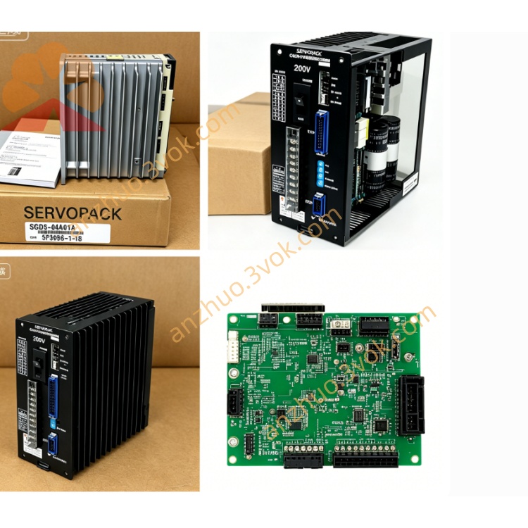
YASKAWA CACR-SR15BA1AF digital AC servo drive under Yaskawa CACR-SR series
The CACR-SR15BA1AF is a digital AC servo drive under Yaskawa CACR-SR series, designed to pair with 1.5kW medium inertia servo motors. It adopts full digital three-loop closed-loop control architecture, integrating power drive, signal processing and motion control circuits into a single compact unit. This model supports dual power input, analog and pulse dual command control, with outstanding low-speed constant torque output and fast dynamic response. It features robust anti-interference capability and flexible parameter configuration, suitable for cabinet-mounted precision motion equipment with medium load demands, and delivers stable positioning and speed control performance for standard automation production equipment.
Description
1. Product Overview
The CACR-SR15BA1AF is a digital AC servo drive under Yaskawa CACR-SR series, designed to pair with 1.5kW medium inertia servo motors. It adopts full digital three-loop closed-loop control architecture, integrating power drive, signal processing and motion control circuits into a single compact unit. This model supports dual power input, analog and pulse dual command control, with outstanding low-speed constant torque output and fast dynamic response. It features robust anti-interference capability and flexible parameter configuration, suitable for cabinet-mounted precision motion equipment with medium load demands, and delivers stable positioning and speed control performance for standard automation production equipment.
2. Model Code Explanation
CACR: Yaskawa general servo drive series identifierSR: Medium capacity standard servo sub-series with integrated internal braking circuit15: Matched rated motor power, 1.5kWBA: Hardware specification code; standard power circuit, single/three-phase 200V class input, simplified basic digital I/O terminal layout, different internal signal circuit layout compared to BB type1: First generation control hardware versionAF: Universal international specification variant, standard industrial signal level, no regional voltage or customized functional limits, compatible with global standard automation hosts
3. Technical Specifications
Input power supports single-phase 200–230V AC or three-phase 200–230V AC, voltage fluctuation tolerance ±10%. Rated output current is 9.6A, peak instantaneous output current reaches 28.8A to realize three times rated short-time overload torque. Control bandwidth maxes out at 400Hz, matching high-resolution incremental encoders with up to 1,310,720 pulses per mechanical rotation. Operating ambient temperature ranges from 0°C to 55°C for continuous running; storage temperature covers -20°C to 70°C, relative humidity 5%–90% without condensation. Unit protection rating is IP20 for cabinet internal installation, vibration resistance conforms to general industrial 10–2000Hz standards. Multiple built-in hardware and software protection functions include overvoltage, undervoltage, overcurrent, overload, overheating, encoder wire breakage and emergency stop interlock. Standard cooling is natural air convection, unit weight is approximately 3.2kg.
4. Interface and Communication Configuration
Position command channel uses differential pulse input for high anti-interference positioning signals. Analog voltage input 0 to ±10V supports switching between speed command and torque command modes. Isolated digital input terminals receive servo enable, alarm reset, origin search and travel limit signals. Digital output terminals provide relay isolated feedback signals including servo ready, positioning completion, speed arrival and fault alarm for external peripheral control. Dedicated encoder terminal block accepts A/B/Z phase differential incremental encoder signals via shielded cables. The unit is equipped with built-in RS422 serial communication port, used for parameter modification, real-time operating data reading and fault history query with Yaskawa handheld operator panel. No fieldbus communication card is pre-installed; optional expansion modules can be added to support bus communication as required. Terminal blocks cover main power input, motor power output, external braking resistor access and grounding terminals, all with locking structures to prevent loose wiring during long-term operation. Every signal interface is equipped with common mode noise suppression circuits to weaken electromagnetic interference in complex factory wiring environments.
5. Core Functions
Full digital independent current, speed and position loop control with separately adjustable gain parameters. Automatic gain tuning function quickly matches mechanical characteristics and suppresses resonance without complex manual parameter setting. Three switchable control modes via parameter setup: position control for high-precision fixed-length positioning, speed control for steady constant-speed operation, torque control for tension control and pressure holding processes. Built-in electronic gear function allows arbitrary gear ratio setting to match different mechanical reduction structures without mechanical modification. Multiple homing modes are supported, including dog-trigger homing and Z-phase signal homing, with adjustable homing speed and position offset parameters. Multi-stage notch filters eliminate low-frequency mechanical vibration during acceleration and deceleration. Short-time triple overload torque output meets rapid acceleration and heavy startup load requirements. Integrated fault self-diagnosis automatically records fault codes and pre-alarm operating data for fast troubleshooting; most minor faults support remote alarm reset without power cycle.
6. Application Scenarios
This servo drive targets medium-load precision automation equipment across general manufacturing industries. Typical applications include automatic feeding mechanisms for small stamping machines, textile winding and unwinding axes, packaging cutting and filling actuators, indexing turntables for electronic assembly, paper feeding and registration axes of printing machines, auxiliary feed axes of small CNC equipment, and positioning platforms for automated testing. It fits light-to-medium load production lines requiring moderate dynamic response and multi-type command signal docking, such as food processing automation equipment, auxiliary motion axes of plastic molding machines, and light sorting conveyor equipment in logistics systems. It can only be installed inside sealed electrical cabinets in indoor workshop environments; additional protective measures are mandatory if deployed in high-dust, corrosive gas or sustained high-temperature working conditions.
7. Operation and Maintenance Instructions
Before power-on installation, verify that the power supply voltage matches the drive rated specification, fasten all wiring terminals firmly, and separate power cables and signal cables with full shielding to reduce signal interference. After initial installation, execute parameter initialization and automatic gain tuning, then adjust speed limits, torque upper limits and soft start-stop parameters according to actual mechanical loads to reduce mechanical impact. During daily operation, judge running status via front panel indicators: steady green light means normal servo operation, flashing red light indicates fault alarm. Under standard workshop conditions, routine maintenance is required every three months: clean cooling air ducts to remove dust blocking heat dissipation, recheck terminal tightening torque, and inspect encoder cable outer sheath for abrasion and damage. When a fault occurs, record the fault code first, cut off main power after the motor fully stops, then inspect wiring and mechanical jamming according to fault definition descriptions. For long-term shutdown, disconnect main power supply; wait 30 minutes before re-powering to avoid short circuits caused by internal circuit condensation. Do not disassemble the internal power module without professional authorization; high-voltage residual charge remains inside after power cut, wait at least 10 minutes before opening the drive cover for inspection. Avoid frequent repeated power-on and power-off within short intervals to protect the internal rectifier circuit. Replace the built-in cooling fan immediately once abnormal noise or slow rotation occurs to prevent overheat shutdown. Store spare drives in dry constant-temperature warehouses with moisture-proof packaging to prevent circuit board oxidation and failure.
Get a Quote