
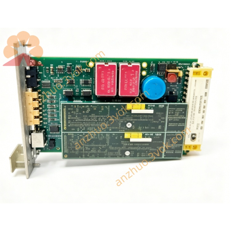
EPRO MMS6312 Dual Channel Rotational Speed Monitor Module For MMS6000 Turbine Protection System
Description
EPRO MMS6312 Dual-channel Speed / Phase Alignment Module (User Manual - No Diagram Version) I. Product Overview
MMS6312 is a dual-channel speed/key-phase monitoring module of the EPRO brand under Emerson. It is a core component of the MMS6000 TSI system and is used for monitoring the speed, zero speed, key-phase, rotation direction, and differential speed of rotating machinery such as steam turbines, compressors, and fans. It supports redundant operation mode and can be hot-swapped while powered on.
II. Model Meaning
MMS6312: Standard dual-channel speed / phase module (without expansion function)
III. Compatible Sensors
Electromagnetic induction sensor: PR6426/6423 series + CON021/CON011 preamplifier
Hall speed sensor: PR9376 series (e.g. PR9376/010-011)
IV. Technical Parameters
Measurement Performance
Number of channels: 2 independent channels (redundant / independent configuration)
Frequency range: 0 - 20kHz (supports 0 rpm zero speed)
Speed range: 0 - 99999 rpm (programmable)
Phase resolution: 1 pulse / revolution (single phase slot)
Accuracy: ±0.01% FS; Temperature drift: ≤ 50 ppm/℃
Input Signal
Induction sensor: -24VDC power supply, input -18 to -2V gap voltage
Hall sensor: 8 to 31.2VDC power supply, input 0 to 24V square wave pulse
Output Signal
Speed current: 2 channels 0/4 - 20mA (isolated, load ≤ 500Ω)
Phase pulse: 2 channels 24V active pulse (1 channel per channel)
TTL pulse: 2 channels 0 - 5V (front panel SMB interface + back panel terminal)
Alarm Output: 4 channels relays (normally open / normally closed, 250VAC/3A)
Electrical and Environmental
Power supply: +18 - +31.2VDC (redundant dual input, ≤ 10W)
Temperature: -20℃ to +70℃; Humidity: 5% to 95% RH (no condensation)
Size: 30 × 128.4 × 160mm; Weight: 0.32kg
Protection: IP20 (module); EMC: Compliant with IEC 61000-6-2/4
V. Working Modes
Independent Mode (Single Channel)
Channel 1/2 separately monitor the speed / phase of 2 axes
Applicable: Dual-axis independent monitoring, one-used-one-busy non-redundant
Redundant Mode (Dual Channels)
Channel 1 main measurement, automatically switch to Channel 2 in case of failure
Applicable: Over-speed protection, critical axis speed monitoring (requires parameter configuration)
Steering / Differential Mode
Dual-channel cooperation: monitor rotation direction, speed difference between two axes
VI. Wiring Definitions (Back Panel Terminals, 32 pins)
Sensor Input (Channel 1)
B02: Sensor signal (induction / Hall)
B04: -24V (induction preamplifier power supply)
B06: 0V (ground)
Sensor Input (Channel 2)
B08: Sensor signal
B10: -24V
B12: 0V
Phase / TTL Output
D14/B14: Channel 1 phase (24V)
D16/B16: Channel 2 phase (24V)
Z14/Z16: TTL pulse (0 - 5V)
Current Output (Speed)
Z18/B18: Channel 1 (0/4 - 20mA)
Z20/B20: Channel 2 (0/4 - 20mA)
Alarm Relay
OUT1 - 4: Programmable alarm (over-speed / zero speed / differential / steering) Power supply
+24V: +18 to +31.2VDC
GND: Power Ground
VII. Configuration (MMS6910 Software)
Basic Parameters
Channel Enable: Channel 1/2 (Independent / Redundant)
Sensor Type: Eddy Current (PR642x) / Hall (PR9376)
Gear Teeth: Number of teeth of the speed measuring gear (e.g. 60 teeth)
Range: 0 to Full Scale (e.g. 0 to 6000 rpm)
Output Mode: 0 to 20mA / 4 to 20mA
Alarm Thresholds
Over-speed: High Alarm / High-High Alarm (e.g. 5400 rpm / 5700 rpm)
Zero Speed: ≤ 1 rpm (Spindle Alarm)
Difference: Difference between two axes (e.g. ±50 rpm)
Direction: Forward / Reverse (Reverseable Setting) Advanced functions
Offset tracking: Compensation for gap drift of eddy current sensors
Steering reset: External pulse / software reset of steering indication
Sensor self-check: Breakdown / short circuit / abnormal gap detection
VIII. Installation and Commissioning
Mechanical Installation
Method: DIN rail (IMR6000 chassis)
Location: Away from the power cabinet, with good ventilation
Spacing: ≥ 20mm from adjacent modules
Connection Points
Sensor cable: Double shielding, single-point grounding (module side)
Eddy current sensor: CON021 preamplifier installed nearby
Hall sensor: PR9376 with a gap of 1.0mm, vertical tooth surface
Power-on Commissioning
Self-check: Green LED always on (normal), red LED flashing (fault)
Signal Verification:
Eddy current: 5.5mm gap, preamplifier output 0V, module shows normal
Hall: Rotating gear, pulse frequency = rotational speed × number of teeth
Calibration: Current output 4mA = 0rpm, 20mA = full scale, accuracy ≤ ±0.05%
IX. Fault Troubleshooting
No rotational speed display
Sensor: Wiring / power supply / abnormal gap (eddy current 5.5mm, Hall 1.0mm)
Configuration: Incorrect number of teeth / range
Module: Channel not enabled / incorrect sensor type selection
Rotational speed fluctuation / oscillation
Interference: Cable close to the frequency converter / motor, poor shielding and grounding
Gear: Tooth surface wear / dirt, material not soft magnetic steel
Power supply: Voltage unstable (≥ 18VDC)
Alarm triggered by mistake
Threshold: Set too low / too high
Offset: Eddy current sensor gap offset (enable offset tracking)
Connection: Shielded double-end grounding, interference introduction
X. Accessories and Selection
Standard Accessories: MMS6312 + PR6426/010-140 + CON021 (eddy current speed)
Hall Accessories: MMS6312 + PR9376/010-011 (Hall speed / phase alignment)
System Accessories: MMS6823 (communication), MMS6210 (extension), DCS/DEH
Get a Quote