
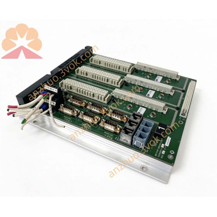
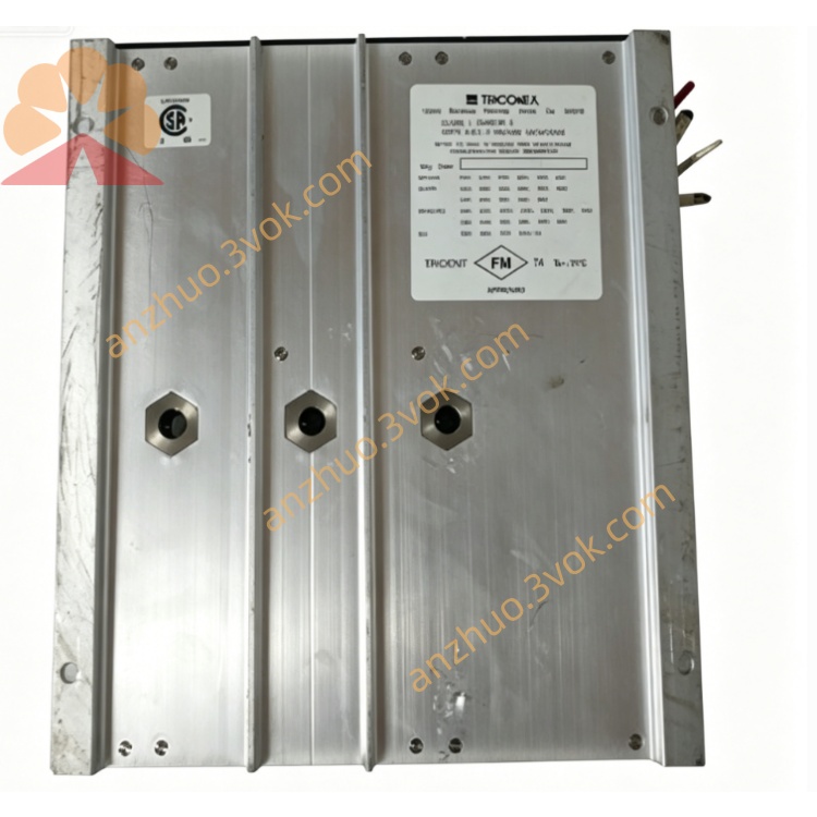
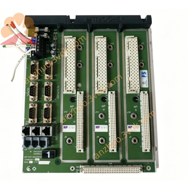
TRICONEX 2101 core triple modular redundant (TMR) Main Processor Module (MP)
Description
1. Product Overview
2. Model Coding & Suffix Variants
TRICONEX: Brand identifier for Tricon TMR safety hardware
2101: Trident series compact main processor hardware model
Suffix options for different environments:
No suffix: Standard indoor cabinet general version
N (2101N): Enhanced EMC anti-interference variant for compressor rooms and coastal plants
-E: English firmware version for overseas projects
-HT: High-temperature variant, stable operating temperature up to +70°C for furnace-side cabinets
3. Core Electrical & Performance Specifications
Backplane power supply: 24VDC from Trident rack backplane, typical power consumption ≤10W, input voltage range 18–30VDC
Core hardware: 32-bit MPC860 RISC processor, 33MHz main frequency
Memory allocation
DRAM: 1MB for real-time logic & process data
Flash PROM: Firmware storage, supports field online upgrade
Battery-backed SRAM: Store SOE logs and hardware fault records, data reserved after power failure
Backplane bus: Proprietary Trident TriBus, communication rate 375 kbps, three mutually isolated redundant channels
External communication interfaces
1×10/100Mbps Ethernet port (Modbus TCP/IP) for HMI/DCS data upload
Isolated RS232 serial port for TriStation program download, maintenance diagnosis
System capacity limit: Max support 512 I/O logical points, configurable logic scan cycle 20ms ~ 500ms
SOE timestamp precision: 1ms for all digital state change, trip and module fault events
Power protection: Built-in backplane undervoltage, overvoltage and overcurrent lockout protection for each redundant channel
4. Functional Safety & Reliability Index
Safety certifications: IEC 61508 SIL 3, IEC 61511, TUV, UL, CE certified
TMR voting logic: Three 2101 processors run identical safety programs synchronously; all I/O sampling values and logic operation results execute hardware 2oo3 voting to shield single-channel calculation deviation and avoid false safety trips
MTTFS (Mean Time To Safe Failure): 260,000 hours
MTTR: 30 minutes, full rack shutdown required for maintenance
Single fault masking: Damage to one processor channel only triggers FAULT alarm; the other two channels maintain complete safety interlock control
Fault storage: All bus communication errors, memory CRC faults, I/O offline alarms and trip events are latched in non-volatile memory for post-accident root cause analysis and factory safety audit
5. Environmental & Mechanical Parameters
Standard operating temperature: -40°C ~ +65°C; -HT variant extended to +70°C
Storage temperature: -40°C ~ +85°C
Relative humidity: 5% ~ 95% non-condensing, cabinet installation IP20 rating
EMC performance: Pass ESD, radiated RF, surge and fast transient burst interference tests; 2101N strengthens anti-salt-fog performance for coastal onshore sites, not recommended for long-term offshore platform deployment
Installation: Single-slot horizontal plug-in in dedicated MP slots of Trident main rack
Cooling: Natural convection cooling, no forced fan required under full load
Vibration resistance: Compliant with small refinery, gas station and auxiliary boiler industrial vibration standards
6. Hardware Interfaces & Front Panel Indicators
Front Panel LED Diagnostic Lights
PASS: Steady green = three redundant processor channels run synchronously without inconsistency
FAULT: Red light = core hardware failure, three-channel voting mismatch or TriBus communication error
ACTIVE: Channel heartbeat running indicator
ETH TX/RX: Ethernet data transmit/receive flashing lights
COM TX/RX: RS232 serial port communication activity lights
Hardware Interfaces
Rear gold finger connector: Triple isolated TriBus backplane bus, realizes cross-data synchronization between three MPs and bidirectional data exchange with all rack I/O modules
Front external ports: RJ45 Ethernet port, 9-pin RS232 maintenance serial port
Mechanical lock handle for module extraction and fixing (power-off disassembly only)
7. Core Key Functions
- TMR Triple-Redundant Synchronous Safety Logic CalculationThree independent 2101 MPs execute the same user ESD/F&G interlock program synchronously, collect all AI/DI/DO pulse I/O data respectively, and output final valid trip/hold commands after 2oo3 hardware voting, eliminating safety shutdown risks caused by single processor hardware failure. Optimized for small-unit simple safety logic with distributed remote I/O layout.
- Full-Rack I/O Data Polling & Centralized Fault DiagnosisEach processor independently polls all local and remote I/O modules via TriBus; uniformly diagnose channel open-circuit, short-circuit and module offline faults, summarize all fault information to the main processor for unified storage and upper-level upload.
- Millisecond-Level SOE Sequence-of-Event RecordingHardware timestamp unit marks all safety trip, digital status change and module fault events, stored in battery-backed SRAM. Historical records will not be lost after rack power cut-off, supporting accident traceability and safety compliance audit.
- Dual Independent External Communication ChannelsSeparate Ethernet for long-term real-time data transmission to plant DCS/HMI; isolated RS232 serial port exclusive for offline program download and fault log reading, two communication channels do not occupy each other’s bandwidth. Supports Modbus TCP standard industrial protocol for third-party system docking.
- Automatic Cross-Channel Program Synchronization & Redundant BackupAll safety programs and system configuration parameters are stored in independent Flash of each 2101. After rack power restart, three MPs automatically synchronize program files to realize triple redundant backup. When replacing a faulty 2101 spare card, the two normal processors automatically copy all complete configurations without repeated manual download.
- Support Fiber Remote I/O Chassis ExpansionMatched with RXM series fiber remote extender modules, the 2101 system can deploy remote I/O cabinets up to 2km away via multi-mode fiber, reducing long-distance field sensor wiring length and lowering electromagnetic interference risks of signal cables.
8. Typical Application Scenarios
Small & medium petrochemical plant single-unit ESD emergency shutdown safety instrument systems
Onshore mini oil & gas station fire and gas detection safety monitoring
Auxiliary industrial boiler overtemperature/overpressure protection SIL 3 systems
Small natural gas pipeline branch compressor station safety interlock control
Low-risk fine chemical single-reactor temperature/pressure safety monitoring
Legacy Trident compact SIS system spare part replacement & renovation projects
9. Installation & Maintenance Guidelines
Installation Restrictions
Platform compatibility: Only matched with Trident series racks and V7/V8 Trident firmware; incompatible with large-scale Tricon classic racks (3003/3005/3006/3008 MP series)
Power-off mandatory rule: Full rack power supply must be completely cut off before plugging or removing any 2101 module; online hot-swap is strictly forbidden
Wiring specification: Ethernet and RS232 cables adopt shielded twisted pair; all cable shields implement single-point grounding only at cabinet ground bar, double-end grounding prohibited to avoid communication packet loss
Slot layout: Install only in three dedicated MP slots of Trident main rack; reserve ≥20cm ventilation gap around the three processors, avoid placing high-power heat-generating I/O modules adjacent to MP cards
Daily Inspection Standards
Visual check: PASS light steady green, no constant FAULT red light; ETH/COM TX/RX lights flash normally during data interaction
Weekly operation: Log into TriStation to export full-system SOE logs and processor fault records for offline backup
Monthly maintenance: Clean dust on front panel indicators, communication ports and rack ventilation slits; check cabinet cooling fan and ambient operating temperature
Regular Inspection Cycle
Standard indoor control room: Full communication test, Flash program CRC integrity verification and backup battery voltage check every 12 months
Coastal salt-fog / high-temperature furnace-side cabinets: Inspection cycle shortened to 6 months
Test items: Three-channel synchronous operation verification, Ethernet/serial communication stability test, backup battery aging replacement when voltage below threshold
Common Fault Handling Steps
Single channel FAULT light permanently lit: Check whether the module mechanical handle is fully locked; inspect backplane connector dust/corrosion and rack 24V power supply voltage
Mass I/O modules offline simultaneously: Cut off full rack power supply, re-seat three 2101 main processors and restart the rack for automatic cross-program synchronization
Internal processor/memory hardware failure: Arrange planned full-unit shutdown maintenance, cut off rack power, replace with identical spare 2101 module, restore power and wait for automatic parameter synchronization, then clear historical fault logs
Prohibited Operations
Spare Module Storage & Service Life
Storage environment: Constant-temperature dry warehouse (0~40°C, RH ≤70%), sealed in original anti-static packaging bags to prevent static damage to internal chips
Shelf maintenance: Conduct 30-minute power-on aging test every 6 months to activate internal circuit capacitors and detect backup battery voltage attenuation
Design service life: 12 years under rated operating conditions; unified batch replacement recommended after expiration to guarantee overall SIS SIL 3 safety integrity level
Get a Quote