1. Product Introduction
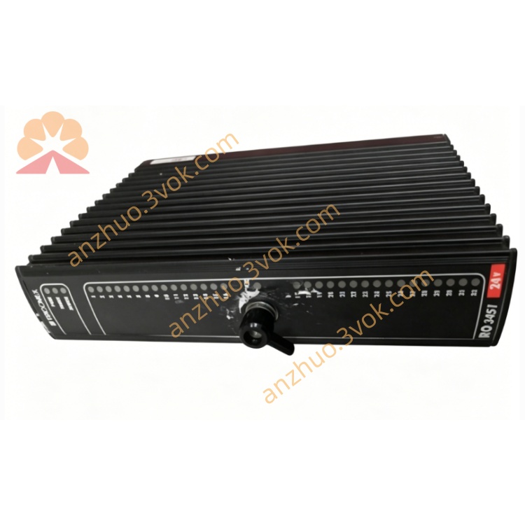
TRICONEX 3451, officially named 32-Channel Solid-State Relay Output Module (SRO), is a TMR safety auxiliary output module under Schneider Tricon safety instrument system, matched exclusively with supporting baseplate 2451 for field wiring connection. It receives triple redundant command signals from three main processors and completes internal hardware two-out-of-three voting to drive 32 independent solid-state relay output channels, mainly used for non-critical safety auxiliary loads such as alarm annunciator panels, remote indicator lights, auxiliary status relays and local HMI signal indication loops.
Different from SIL3 critical supervised safety output modules (3624, 3725) used for ESD trip valves, the 3451 focuses on high-density status signal distribution without full loop supervision for safety trip loads, but retains complete channel fault self-diagnosis and electrical isolation design. It cannot support online hot-swap replacement; full rack power-off is required for disassembly and maintenance. It runs stably 24/7 in wide-temperature, vibration industrial environments, single internal circuit fault will not interrupt overall channel output, widely deployed in petrochemical, onshore oil & gas stations, thermal power and chemical plant SIS auxiliary signal distribution systems.
2. Model Definition Explanation
The complete model TRICONEX 3451 consists of brand identifier, core hardware classification code and optional configuration suffixes, must be paired with baseplate 2451 terminal base:
Prefix TRICONEX: Brand mark, representing Tricon TMR safety control hardware series, separated from non-safety general automation I/O modules.
Four-digit core number 3451: Internal rack relay output module classification coding. The first digit "3" stands for digital input/output category; the middle two digits "45" mark solid-state relay high-density output circuit layout; the last digit "1" represents base 32-channel paired common solid-state relay output hardware platform.
Optional suffix configuration codes for differentiated project demands:
No extra suffix: Standard indoor control room main module body, matched with 2451 baseplate for field wiring.
-E: Full English firmware variant, all front panel fault codes, diagnostic prompts and TriStation configuration text display in English for overseas international projects.
-HT: High-temperature extended variant, raising stable upper operating temperature to +70°C for high-heat workshop cabinets.
3. Technical Specifications
Electrical Performance
The module draws 24VDC operating power from Tricon rack backplane, rated power consumption below 9W, allowable input voltage fluctuation 20VDC ~ 30VDC. Equipped with 32 solid-state relay output channels, grouped in 16 pairs of commoned channels, each channel independent galvanic isolation.
Single channel rated resistive load power: Max 15W
Nominal continuous output current: 0.5A per channel, overcurrent protection threshold 0.7A
Isolation withstand voltage: 800VDC between internal logic and field load side, 500VDC between channels and protective earth
Off-state leakage current: Less than 100μA, effectively avoiding false actuation of low-power indicator loads
Built-in 0.75A fast fuses integrated on matched 2451 baseplate for independent channel overcurrent protection
Full 32-channel state full-scan refresh cycle: ≤25ms, each output state frame carries millisecond timestamps for SOE sequence recording
No built-in loop supervision circuit for load coil open/short detection, only circuit overcurrent and fuse blow fault diagnosis; single-channel fuse fault only cuts off corresponding channel without affecting other output loops and main safety logic.
Functional Safety & Reliability Index
TRICONEX 3451 fully complies with IEC 61508 SIL3 and IEC 61511 process safety standards, holding UL, CE, ATEX industrial safety certifications. Three-way redundant command signals from main processors execute strict two-out-of-three internal voting logic before driving solid-state relays, eliminating false output caused by single logic channel abnormality. Hardware mean time to safe failure reaches 290,000 hours; mean time to repair is controlled within 30 minutes due to mandatory rack power-off maintenance rules. It has basic single-fault masking capability; partial channel fuse damage or single redundant circuit failure will not lead to full-module output failure. All overcurrent and fuse fault alarms are latched and stored in non-volatile memory for safety audit traceability.
Environmental & Mechanical Parameters
Standard model operating temperature range: -40°C ~ +65°C; HT high-temperature variant extends upper limit to +70°C. Spare module storage temperature: -40°C ~ +85°C, suitable for long-term warehouse storage. Tolerable relative humidity: 5% ~ 95% without condensation, cabinet installation protection grade IP20. Passes complete industrial EMC tests including electrostatic discharge, radiated RF interference, surge impact and fast transient pulse interference. Designed for single-slot horizontal installation in standard Tricon safety I/O racks, no forced air cooling required under full rated load. Vibration resistance meets onshore petrochemical, thermal power and conventional gas station standards; long-term low-frequency continuous vibration will not cause solid-state relay drive failure or false output. Not recommended for offshore platforms with continuous severe salt fog corrosion.
4. Interface and Communication Configuration
Hardware Interface Layout
The module has two independent hardware interface categories: rear internal backplane system interface and front matched baseplate wiring interface.
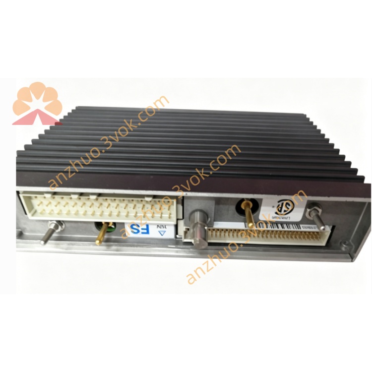
The rear gold finger dedicated connector is proprietary Tricon TriBus TMR backplane bus interface, responsible for redundant power supply intake, three-way isolated bidirectional command and fault data exchange between the module and three redundant main CPUs, real-time uploading of module hardware faults and channel fuse overcurrent fault codes to rack mainframe.
The front panel is equipped with dense multi-color LED grouped diagnostic indicators, including global PASS normal running indicator, global FAULT hardware alarm indicator, independent ON/OFF status light for each of the 32 channels, enabling maintenance personnel to directly judge field auxiliary indicator and relay operating status at the cabinet without remote HMI viewing. All field load wiring terminals are arranged on supporting 2451 baseplate with screw-type terminals and shielding grounding terminals per group, supporting crimp connection of shielded twisted-pair cables for alarm panel and indicator wiring construction.
Internal Backplane Communication Mechanism
Data interaction between TRICONEX 3451 and triple redundant main processors relies on three fully isolated proprietary high-speed TriBus backplane buses, one-to-one corresponding to the three internal voting processing circuits of the module. Each redundant bus independently transmits auxiliary output control commands and channel fault diagnostic data from each CPU to the SRO module. Before triggering solid-state relay output, the module executes two-out-of-three hardware voting on three groups of synchronous control commands to eliminate signal inconsistency caused by single CPU deviation. Faults such as backplane link disconnection, communication timeout and data parity errors light the front panel global red FAULT indicator and upload detailed fault location codes to TriStation configuration software and central monitoring HMI.
Output Channel Configuration Mode
The module has no independent Ethernet or serial ports; all channel safe failure state definition and output logic parameters are downloaded and stored in Tricon main processor redundant memory, automatically synchronized to the 3451 module after full rack power restart. Operators can independently configure each channel’s safe state through TriStation software: set to OFF cut-off state when module or communication fails for alarm indicators, set to ON hold state for continuous status display auxiliary relays. Channel grouping mode is fixed in hardware (paired common channels), and cannot be modified by software configuration.
5. Core Functions
Triple Redundant 32-Channel High-Density Solid-State Relay Auxiliary Output
Three redundant logic circuits synchronously receive auxiliary status output commands from mainframe, and drive solid-state relays only after passing two-out-of-three voting verification, avoiding false lighting/actuation of field alarm panels and auxiliary relays caused by single circuit abnormality. 32-channel high-density design greatly saves cabinet slot space for mass auxiliary signal distribution loops, single-channel fuse overcurrent fault only triggers local channel status abnormality without interfering with normal output of other independent auxiliary signal loops.
Per-Channel Overcurrent and Fuse Blow Fault Diagnosis
Continuous background diagnosis monitors each solid-state relay output channel, identifying two core fault modes: channel overcurrent load and built-in baseplate fuse blow. All detected channel faults light the corresponding channel abnormal status indicator on the front panel, uploading fault channel serial number, fault occurrence timestamp and fault classification codes to central monitoring platform. Single-channel fault will not shut down full-module output function, all historical fault records can be exported for factory safety compliance audit and system abnormality analysis.
Full Rack Power-Off Replacement Maintenance
The module does not support online hot-swap; full rack power supply must be cut off before plugging and disassembly. After inserting a spare 3451 module of the same model and locking front fastening screws, restore rack power, the Tricon mainframe automatically completes hardware identification, redundant channel synchronization and all channel configuration parameter copying within 30 seconds; all 32 output channels resume normal drive and fault diagnosis functions without manual reconfiguration.
Independent Channel Electrical Isolation and Anti-Interference Protection
Each solid-state relay channel is equipped with independent isolation barriers with 800VDC withstand voltage, limiting abnormal energy cross-transmission between field auxiliary equipment and internal TMR safety circuits, blocking lightning surges, static electricity and transient overvoltage from damaging core rack mainframe hardware. All field auxiliary signal cable shielding layers must adopt single-point grounding at control room cabinet ground bar to eliminate ground loop interference from long-distance workshop wiring. Internal circuit partitioning separates each group of paired output channels to avoid adjacent channel signal crosstalk leading to false status indication.
Configurable Safe Failure State Matching Auxiliary Loads
Through TriStation configuration software, operators can independently define the failure safe state of each output channel to match different types of auxiliary indication equipment. For normally-off alarm lights, configure channel to cut off power automatically upon module failure; for running status holding relays, configure channel to maintain output upon communication loss, realizing differentiated safety state control for different auxiliary signal loops.
Visual Independent Channel On-Site Status Prompt
The front panel carries independent ON/OFF status indicator lights for all 32 channels. Maintenance personnel can directly check the actual energized state of on-site alarm panels, status lights and auxiliary relays at the cabinet, rapidly locating abnormal signal channels without logging into the control system, improving daily inspection and troubleshooting efficiency of mass auxiliary signal loops.
6. Applicable Scenarios
Petrochemical Refining SIS Auxiliary Alarm Signal Distribution Systems
Used as high-density auxiliary output module for crude oil distillation, catalytic cracking and hydrogenation unit safety racks, driving field ESD/F&G alarm annunciator panels, local area fault indicator lights and safety status auxiliary relays, centralized distributing hundreds of non-trip auxiliary status signals with minimal cabinet slot occupation.
Onshore Oil & Gas Station Fire and Gas Auxiliary Indication Systems
Adapted to onshore station control room environments with moderate humidity and vibration, driving wellhead equipment running status lights, gas concentration pre-alarm indicator panels and station fire alarm auxiliary interlock relays; matched with external safety isolation barriers to meet Class I hazardous area cabinet deployment requirements.
Natural Gas Transmission Pipeline Compressor Station Auxiliary Monitoring Systems
Serves station safety interlock racks, driving widely distributed pipeline valve group position indicator lights, compressor unit fault alarm panels and storage tank liquid level pre-alarm auxiliary relays, realizing unified auxiliary status display for dispersed pipeline equipment.
Conventional Thermal Power Plant Boiler Auxiliary Safety Indication Systems
Applied in medium-sized boiler SIS racks, driving furnace flame pre-alarm lights, drum water level abnormal indicator panels and auxiliary turbine protection status relays, realizing high-density real-time display of boiler non-trip auxiliary safety parameters.
Medium-Sized Fine Chemical Non-Offshore Production Workshop Auxiliary Alarm Systems
Deployed in Class I explosive hazardous area control rooms with matched external safety isolation barriers, driving reactor temperature/pressure abnormal alarm lights, toxic gas pre-alarm indicator panels and workshop local emergency stop status relays, centralized distribution of multi-workshop auxiliary alarm signals.
Coal Chemical and Hazardous Waste Incineration Plant Onshore Auxiliary Signal Control
Suitable for onshore production plants with high-dust indoor environments, driving incinerator equipment fault indicator lights, flue gas pressure abnormal alarm panels and storage tank overflow pre-alarm auxiliary relays, maintaining stable high-density solid-state relay output performance under harsh field indoor conditions.
7. Operation and Maintenance Instructions
Installation Requirements
TRICONEX 3451 main module must only be installed in dedicated auxiliary relay output single slots of standard Tricon TMR safety I/O racks, full rack power supply must be completely cut off before plugging and disassembly, online hot-swap is strictly prohibited. Insert the module horizontally into the card slot, fully lock front panel fastening screws to guarantee reliable contact between rear backplane gold finger connector and rack bus. Must be matched with supporting 2451 wiring baseplate for field load wiring connection. All field auxiliary load cables adopt double-shielded twisted-pair industrial cables; cable shielding layers must be single-point grounded at control room cabinet ground bar, multi-point grounding on field indicator/relay side is strictly prohibited to prevent ground loop induced interference. For hazardous area cabinet installation, certified safety isolation barriers must be added between baseplate output terminals and field auxiliary equipment, strictly complying with intrinsic safety circuit parameter matching specifications. A ventilation gap of at least 15 centimeters must be reserved around the rack card slot; high-power heat-generating modules cannot be stacked beside the 3451 module to avoid overheating exceeding rated operating temperature and triggering channel overcurrent protection faults.
Daily Routine Inspection Standards
Conduct daily visual inspection to confirm front panel PASS indicator stays steady green, global FAULT alarm light remains off, each channel ON/OFF status light matches actual on-site auxiliary equipment operating state without abnormal fault indication. Log in to TriStation configuration software or system central HMI every day to check all 32 output channel operating status, confirming no records of channel overcurrent, fuse blow or internal hardware faults. Every week, compare module-displayed channel output state with field auxiliary equipment actual status to judge abnormal solid-state relay false actuation or signal loss. Every month, clean dust accumulated on module front indicators, 2451 baseplate wiring terminals and rack ventilation slits, check cabinet cooling fan operation status, ensure ambient temperature around the module stays within specified -40°C ~ +65°C operating range.
Regular Inspection and Calibration Cycle
Under standard indoor control room conditions, full output channel drive function test and fuse inspection shall be performed every 12 months; for coastal salt-fog workshops and high-temperature chemical production areas, the inspection cycle is shortened to 6 months. Before inspection, back up all channel safe state configuration parameters stored in Tricon main processor redundant memory. Use adjustable load simulators to inject standard resistive load signals into each channel group one by one, verify normal solid-state relay drive function and accurate overcurrent fault judgment, replace aged fuses on 2451 baseplate regularly. After completing all channel tests, save updated configuration data to redundant system memory, retain written inspection records including inspection date, operator name and fault test data for factory safety compliance audit.
Common Fault Handling Procedures
When a single channel abnormal status indicator lights up, first inspect the corresponding field auxiliary relay/indicator load and output wiring for short circuit overload, check whether the matched baseplate channel fuse is blown, replace damaged fuses or rework wiring after eliminating external load faults. If front panel global FAULT red light is permanently lit and multiple channel groups lose output simultaneously, cut off full rack power supply first, then check rack 24VDC power supply voltage and whether backplane connector has dust accumulation, corrosion or poor contact. If system diagnostics report internal voting circuit hardware failure of the module, planned shutdown maintenance must be arranged: cut off rack power, unlock front fastening screws, steadily pull out faulty module, insert spare TRICONEX 3451 module of the same suffix version, lock screws tightly, restore rack power supply, wait for mainframe automatic synchronization of channel configuration parameters to complete, then verify all 32 output channels resume normal drive and diagnosis functions and clear historical fault alarm logs. On-site disassembly of internal circuit components is forbidden; damaged modules must be returned to official authorized service centers for repair or scrapping. Unauthorized disassembly invalidates all SIL3 safety certifications of the hardware.
Spare Module Storage and Long-Term Service Management
Offline spare TRICONEX 3451 modules shall be stored in constant-temperature dry warehouse with ambient temperature maintained at 0°C ~ 40°C and relative humidity controlled below 70%. Modules must be sealed in original anti-static packaging bags to prevent static electricity damage to internal voting and solid-state relay drive chips, avoiding direct sunlight, corrosive gas and heavy dust environments. Every six months of shelf storage, take out spare modules for a 30-minute power-on aging test to activate internal circuit capacitors and prevent component performance degradation from long-term power-off state. The module’s design service life under rated normal operating conditions is 15 years; all on-site installed 3451 modules shall be batch-replaced upon reaching service life to maintain overall SIL3 safety integrity level of the entire SIS system.
Maintenance Safety Prohibitions
Unauthorized modification of internal voting chips, independent firmware flashing or hardware wiring transformation of TRICONEX 3451 is strictly prohibited. Any modification voids functional safety certification and related industrial safety qualification certificates. Do not connect field loads with instantaneous power exceeding 15W per channel to output terminals for long durations; continuous overcurrent will permanently burn internal solid-state relay drive circuits and baseplate fuses. All maintenance operations involving module plugging, field auxiliary cable replacement or channel safe state parameter modification must be performed by certified SIS safety instrument maintenance personnel, full rack power supply must be cut off before module disassembly. Safety isolation measures for production safety auxiliary signal loops must be implemented before operation to avoid accidental false alarm triggering during maintenance. Module disassembly and replacement is forbidden during critical production startup, shutdown or emergency accident handling stages; all maintenance work must be scheduled during planned equipment shutdown maintenance windows. This module is not suitable for new offshore platform SIS projects due to limited anti-salt fog corrosion performance and lack of safety trip loop supervision function.

Get a Quote