
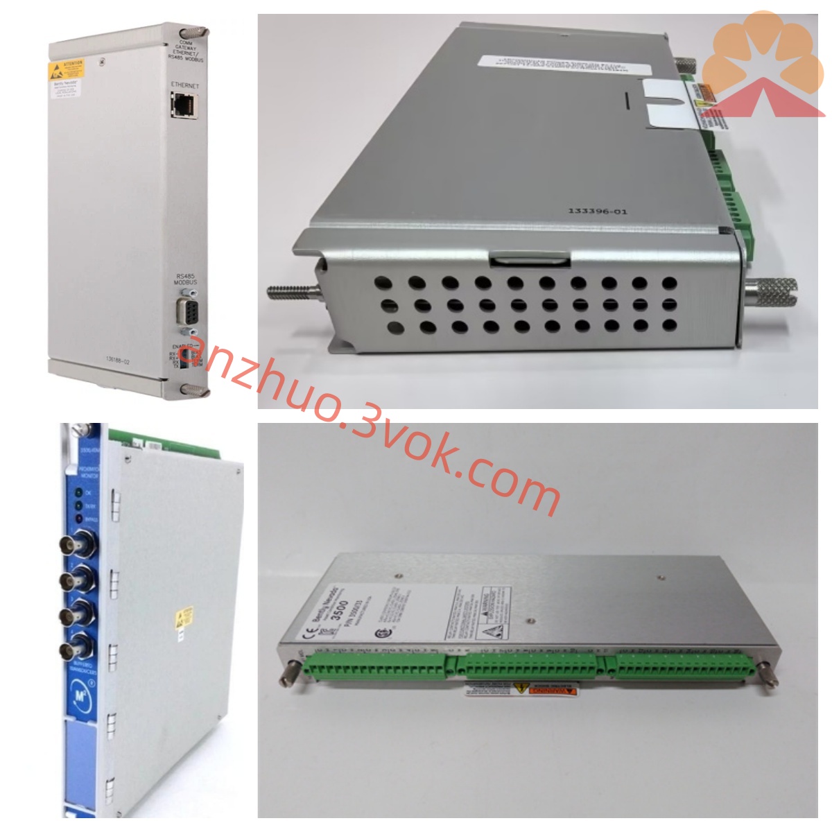
Bently Nevada 3300/25-01-12-12-00-00-01-00 Dual Accelerometer Vibration Monitor Module
Description
Bentley 3300/25-01-12-12-00-00-01-00 Dual Channel Acceleration Vibration Monitoring Module Detailed Product Description
I. Product Overview
The Bentley 3300/25-01-12-12-00 is a dual-channel accelerometer monitoring module within the 3300 series TSI (Turbo Generator Monitoring System) of Baker Hughes (formerly GE Bentley Nevada), specifically designed for online monitoring of medium and high-frequency absolute vibration of industrial large-scale rotating machinery casings, bearing seats, gearboxes, and equipment bases. The module adopts a dual-channel same-range independent architecture, is compatible with standard piezoelectric accelerometers, integrates high-precision signal conditioning, wide-band fixed filtering, single-channel sealed relay output, hardware self-diagnosis, and backplane bus communication functions, supports 19-inch standard rack hot-swappable installation, and can be mixed with other modules in the 3300 series for cabinet assembly. It is widely used in power generation, nuclear power, petrochemicals, metallurgy, air separation, and other industries, providing vibration status monitoring, early fault warning, and safety protection for key equipment such as steam turbines, gas turbines, centrifugal compressors, high-speed fans, and industrial pump sets, in accordance with API 670 industry standards. It is a core component of the rotating machinery condition monitoring system.
II. Model Code Interpretation (3300/25-AA-BB-CC-DD-EE-FF-GG)
3300: Bentley 3300 modular TSI system platform, backplane centralized power supply, rack-mounted installation, hot-swappable architecture.
25: Function category code, representing dual-channel accelerometer monitoring (Dual Accelerometer Monitor).
01 (AA): A channel range configuration, 0–1g (peak), compatible with 100mV/g standard piezoelectric accelerometers.
12 (BB): B channel range configuration, 0–50g (peak), compatible with 100mV/g standard piezoelectric accelerometers.
12 (CC): Filter combination configuration, high-pass 10Hz / low-pass 10kHz, suitable for medium and high-frequency vibration monitoring scenarios.
00 (DD): Certification configuration, no special industry certification, standard industrial grade.
00 (EE): Isolation configuration, no external isolation devices, standard electrical isolation design.
01 (FF): Relay configuration, single-channel epoxy-sealed SPDT relay, achieving warning / danger single-stage alarm output.
00 (GG): Output configuration, standard configuration has no analog output, focused on monitoring, alarming, and data upload.
III. Core Functions
1. Dual-channel independent high-precision vibration acquisition
Equipped with two completely independent signal input channels, A channel 0–1g, B channel 0–50g, differentiated design for different vibration intensities of medium and high-frequency measurement points (such as high-speed bearings, gearbox meshing parts, high-speed equipment base). Compatible with industrial general piezoelectric accelerometers (standard sensitivity 100mV/g), using zero peak (0–p) measurement mode, original frequency response 10Hz–15kHz, after 10Hz high-pass, 10kHz low-pass filtering, effectively monitoring frequency band 10Hz–10kHz, accurately capturing medium and high-frequency fault characteristics such as high-speed rotation looseness, bearing rolling body wear, high-frequency gear meshing impact, and structural high-frequency resonance. The overall measurement accuracy ≤ ±0.5% FS, resolution 0.001g, capable of identifying small high-frequency vibration changes, early warning of early faults. Real-time monitoring of sensor breakage, short circuit, overload / underload in the circuit, compatible with dust, humidity, strong electromagnetic interference, etc. harsh working conditions.
2. Single-channel sealed relay single-stage alarm output Each monitoring channel can independently set the warning or danger single-level alarm threshold. It supports on-site panel local configuration or remote configuration of the upper system. The alarm delay can be adjusted from 0 to 10 seconds, effectively filtering instantaneous vibration disturbances and avoiding false alarms. A single-channel epoxy-sealed SPDT relay is configured, with dust-proof, moisture-proof, and vibration-resistant characteristics. The rated load of the contacts is 2A/24VDC, and it can be directly connected to on-site sound and light alarm devices, DCS control systems, PLC logic circuits, or unit emergency shutdown interlock circuits to achieve single-level safety alarm and interlock protection after vibration exceeds the limit.
3. High-frequency and medium-frequency optimized fixed filtering processing
An internal fixed filtering circuit is built-in. The machine is fixedly configured with a 10Hz high-pass filter and a 10kHz low-pass filter combination. The high-pass filtering can isolate DC components and extremely low-frequency environmental disturbances, focusing on medium-frequency vibration signals; the low-pass filtering can filter out ultra-high-frequency electromagnetic noise and mechanical shock interference, maximizing the retention of medium-frequency fault characteristic signals. The filter parameters can be adjusted through internal jumpers (up to over 10,000 combinations of high-pass/low-pass), adapting to the frequency characteristic requirements of different high-speed rotating equipment and structures, and improving the targeting and accuracy of signal recognition.
4. Full-dimensional hardware self-diagnosis
It monitors the backboard power supply voltage, internal hardware circuits, signal input circuits, filtering units, and relay working status 24/7. Once there is an abnormal power supply, module hardware failure, sensor line failure, or signal abnormality, the corresponding status indicator lights on the equipment panel (OK/Alert/Danger/Fault) will immediately light up and display the fault code, helping maintenance personnel quickly locate the fault location and type, and shorten the maintenance time. The hot-swappable function is supported, and the entire system can complete module replacement and maintenance without stopping, effectively reducing equipment downtime losses.
5. System integration and anti-interference design
A metal shielding shell is used, and multiple electrical isolations are provided between the internal signal circuits, power circuits, and output circuits. The insulation strength between the input and power is ≥2500VAC. It has excellent anti-EMI/RFI electromagnetic interference capabilities. Seamless integration with the 3300 series backplane bus, it can be connected to the Bently System 1 equipment status management platform to achieve remote upload, trend query, data storage and analysis of real-time vibration data, alarm status, and fault records. At the same time, it can be connected to the factory DCS, PLC, SCADA and other automation systems through the bus protocol, integrating into the full-factory automation control system to meet the usage requirements of modern factories for centralized monitoring and predictive maintenance.
Four. Detailed technical parameters
Measurement and input parameters
Number of channels: 2 independent measurement channels.
Compatible sensors: Standard piezoelectric accelerometers, rated sensitivity 100mV/g.
Measurement range: Channel A 0–1g (peak), Channel B 0–50g (peak).
Frequency response: Filtered 10Hz–10kHz, original 10Hz–15kHz.
Measurement accuracy: ≤±0.5% FS.
Measurement mode: Zero peak (0–p).
Input impedance: ≥100kΩ.
Electrical parameters
Power supply: -24VDC (±10%), supplied by the system backplane.
Overall power consumption: ≤5W.
Relay output: 1×SPDT epoxy-sealed relay, rated load 2A/24VDC.
Electrical isolation: Insulation strength between input circuits and power circuits ≥2500VAC.
Analog output: None.
Environmental and mechanical parameters
Operating temperature: 0℃–+65℃.
Storage temperature: -40℃–+85℃.
Operating humidity: 5%–95% (no condensation).
Installation method: 19-inch standard rack slot installation, supporting hot-swappable.
Dimensions: Approximately 203mm × 330mm × 51mm.
Equipment weight: Approximately 0.85–1kg.
Protection level: IP20 (suitable for installation inside indoor control cabinets).
Compliance and Certification
Industry standards: Compliant with API 670 Rotating Machinery Monitoring Protection Standard.
Electromagnetic compatibility: Certified by CE, in accordance with EN 61000-6-2/4 specifications.
Environmental directives: Meets RoHS environmental requirements. V. Typical Application Scenarios
Electric Power Industry: Monitoring of high-speed turbine and generator high-speed bearing housings and precision gearboxes for vibration in thermal power and nuclear power plants. Detection of faults such as rolling element wear in bearings, high-frequency pitting of gears, and structural high-frequency resonance.
Petrochemical Industry: Monitoring of large high-speed centrifugal compressors, high-speed process pump sets, and heavy-duty high-speed motor housings for vibration. Adapted for dusty, oily, and humid conditions to ensure continuous production.
Metallurgical Industry: Monitoring of high-speed sintering fans and high-speed reducers for bases in rolling mills, identifying structural high-frequency loosening, mechanical imbalance, and high-speed transmission mechanism faults.
General Industry: Monitoring of high-speed gas turbines, large high-speed pumping stations, air separation high-speed equipment, and precision high-speed gearboxes for rotating machinery. Providing mid-high frequency vibration data support for equipment condition assessment, fault analysis, and preventive maintenance.
Six. Installation and Commissioning Specifications
Installation Requirements
Frame Installation: Insert the module smoothly into the vacant slot of the 3300 series frame, ensure that the back connectors are fully engaged, tighten the panel fixing screws to ensure reliable contact; reserve sufficient ventilation space around the module to avoid heat accumulation affecting heat dissipation and equipment performance.
Sensor Installation: Piezoelectric acceleration sensors must be rigidly fixed at positions where the vibration transmission effect of the measured equipment is good. The sensor base should be closely adhered to the measured surface; select matching dedicated shielded cables for signal cables, with the shielding layer only grounded at one end of the control cabinet and prohibiting grounding at both ends to form a circulating interference. During wiring, keep away from high-power motors, frequency converters, and other strong electromagnetic equipment.
Wiring Specifications: Strictly distinguish the excitation lines, signal lines, and ground lines for sensors. Ensure the connection terminals are tightened properly to avoid false connections or loosening; distinguish the common terminal, normally open contacts, and normally closed contacts in the relay output circuit, and repeatedly check the circuit continuity after wiring.
Commissioning Steps
After the backplane power supply, the module automatically performs the entire machine self-check. The OK indicator light on the panel remains constantly on, indicating normal hardware self-check. If the fault indicator light is on, check the power supply, wiring, sensors, and module body one by one.
According to the operating process requirements of the on-site equipment, enter the parameter setting interface through the panel buttons, set the single-level alarm threshold and alarm delay time for the two channels, and complete the parameter saving.
Confirm that the filtering parameters of this machine meet the requirements for mid-high frequency monitoring. If adjustment is needed, complete the configuration through the internal jumpers of the equipment.
After the equipment is loaded into operation, observe whether the vibration values of the two channels are stable and without abnormal jumps. Confirm that the sensor circuits have no fault indications.
Manually simulate extreme conditions to test the relay action status, verify the accuracy and correctness of the alarm and interlock logic, and then the module is officially put into operation.
Seven. Maintenance and Fault Troubleshooting
Daily Maintenance
During the inspection process, observe the status of the module panel indicator lights and the real-time vibration values to confirm no alarms or fault indications.
Regularly check all connection terminals to see if there is any looseness, oxidation, dust accumulation, or moisture, and check if the outer skin of the cables is damaged.
Keep the frame ventilation smooth and regularly use a dry soft cloth to clean the dust on the module surface. Do not allow liquids or metal debris to enter the equipment interior.
Regular Calibration
Calibrate the module annually using a professional standard vibration table to verify the vibration measurement values, alarm thresholds, and relay action points to ensure the accuracy and reliability of the entire machine's measurement and protection functions. Record and archive the calibration data.
Common Fault Troubleshooting
OK indicator light goes out: First, check if the 24V DC power supply on the frame backplane is normal. Reinsert and remove the module to check for poor contact issues. If ineffective, determine it as a module hardware fault and replace the module directly.
Vibration values frequently jump: Focus on checking if the sensor installation is loose, if the lines are broken or short-circuited, and if the grounding method is incorrect. Investigate the on-site strong electromagnetic interference sources. If necessary, replace the sensor or signal cable. Frequent false alarms: Verify the rationality of the alarm threshold and alarm delay settings, check if the filtering parameters are incompatible with the high-frequency vibration characteristics of the equipment, and optimize the wiring shielding measures.
No alarm output from the relay: Check the wiring of the relay circuit and the contact status, and investigate whether there is a circuit break or contact damage.
Sensor circuit fault indication: Check the continuity of the cables, the integrity of the sensor, and the wiring polarity section by section. Replace the faulty components.
VIII. Usage Notes
This product is a standard industrial non-explosion-proof device. Installation and use are strictly prohibited in flammable and explosive hazardous areas.
It is only compatible with 100mV/g standard piezoelectric accelerometers. It is forbidden to connect eddy current sensors, platinum resistors, thermocouples and other types of sensing equipment, otherwise it will cause measurement failure or hardware damage.
It is specifically used for high-frequency absolute vibration monitoring in the casing and structure. It cannot be used as an axis vibration or axis displacement monitoring device.
Do not disassemble the module shell privately, modify the internal circuitry, or replace non-original components. Illegal operations will cause permanent damage to the equipment and result in the loss of product warranty services.
Before conducting wiring, maintenance, or disassembly operations, it is necessary to cut off the total power supply of the frame to prevent electric shock and short circuit accidents; during the operation of the equipment with power on, it is strictly prohibited to plug in or unplug the module or touch the internal wiring terminals.
When the equipment is in long-term storage, it is recommended to remove the module from the frame, place it in a dry, cool, and ventilated environment, and avoid moisture, high temperature, and dust accumulation to accelerate the aging of electronic components.
Get a Quote