
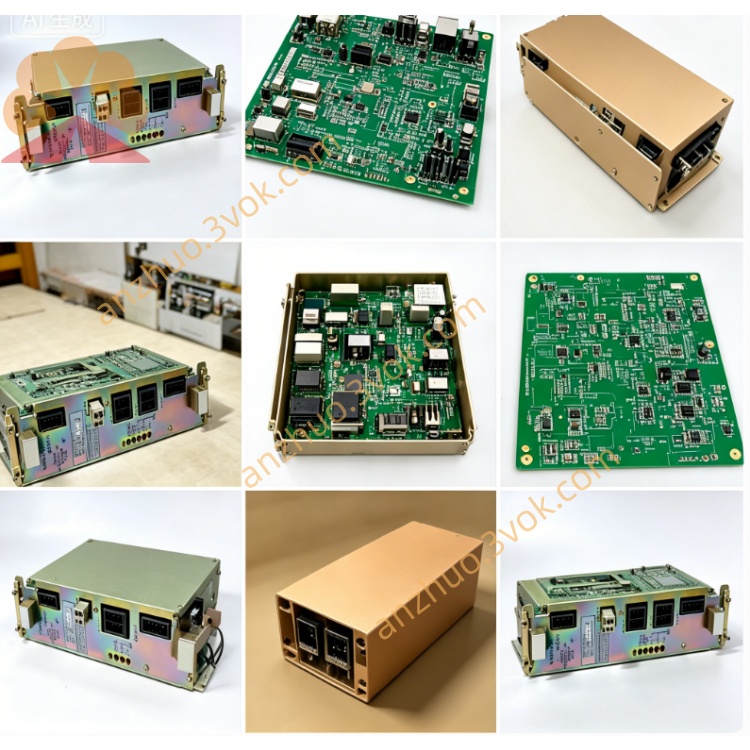
YASKAWA DF9200745-A0 JANCD-SV02C Servo Control PCB
The DF9200745-A0, officially designated JANCD-MIO02 Rev A0, is a standard digital I/O board for Yaskawa Motoman MRC and XRC robot controllers. It adopts natural convection cooling inside the control cabinet and features full optocoupler isolation for all signal channels. This board serves as the signal interface between the controller and field peripherals, delivering reliable signal transmission and strong anti-interference performance for general industrial robot automation applications.
Description
Model Definition
DF9200745: Base part number of MIO02 series general I/O boardA0: Original standard hardware revision with stable circuit layout and universal compatibilityJANCD-MIO02: Official Yaskawa model designationApplicable System: Motoman MRC and XRC robot control platforms
Technical Specifications
Electrical Parameters
Internal supply voltage: 5 V DC for board operation, powered by controller main circuitField control power: 24 V DC, operating range 20 V DC to 28 V DCTotal input channels: 32 optically isolated digital inputsTotal output channels: 32 optically isolated digital outputsSingle channel load current: Max. 0.3 A per output channelOperating current: Approximately 1.2 AIsolation voltage: 500 Vrms between field side and internal circuitPower dissipation: Approximately 18 W
Mechanical & Environmental Parameters
Cooling method: Internal cabinet natural convection air coolingProtection class: IP20 for cabinet internal installationOperating temperature: 0 °C to +55 °CStorage temperature: -20 °C to +70 °CRelative humidity: 30% to 95% RH, non-condensingDimensions (W×H×D): 220 mm × 150 mm × 25 mmWeight: Approximately 0.55 kg
Interface and Communication Configuration
Terminal block: External I/O terminal for connecting sensors, switches and actuatorsSystem bus interface: Dedicated internal bus for data communication with main control boardPower terminals: 24 V DC field power and internal power input portsStatus indicators: Independent LED indicators for each input and output channel
Core Functions
Realize signal collection from external sensors, limit switches and safety devices via digital inputs.Drive external actuators such as relays, solenoid valves and indicator lights via digital outputs.Adopt optocoupler isolation design to suppress on-site electromagnetic interference effectively.Transmit I/O status data to main CPU board in real time for unified logic scheduling.Built-in overcurrent and short-circuit protection for each output channel to avoid hardware damage.Support standard robot peripheral logic control and interlock signal configuration.Modular design enables flexible expansion of I/O quantity for different automation demands.
Application Scenarios
General-purpose Motoman MRC and XRC six-axis industrial robotsRobot workstations for material handling, assembly, polishing and machiningProduction lines with various sensors, solenoid valves and safety interlock devicesRobot controller maintenance, spare part replacement and system reconstruction projectsSmall and medium-sized multi-station automated production cells
Usage and Maintenance
Use ESD protection tools during board disassembly, installation and replacement.Verify 24 V DC field power voltage within the normal range before power-on.Check channel LED indicators regularly to judge working status of each I/O point.Clean terminal blocks and board surface every six months to remove dust and oxide.Tighten loose wiring terminals periodically to prevent poor signal contact.Avoid overloading single output channel to trigger overcurrent protection.Inspect internal bus connectors for looseness to ensure stable data transmission.
Get a Quote