
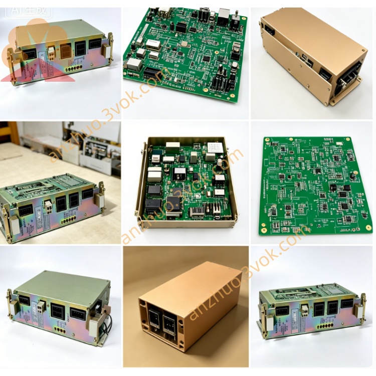
YASKAWA JANCD-CG20B DF8202624 CNC Graphic Board
Description
1. General Information
1.1 Model & Part Number
Model: JANCD‑CG20B
Part No: DF8202624
Type: 4‑axis servo control expansion board for YASNAC i80 / MX3 / PC NC CNC systems
1.2 Features
4 independent servo axes control
MECHATROLINK‑II/III communication
Ethernet 10/100 Mbps(TCP/IP)
A/B/Z phase differential encoder interface;BiSS absolute encoder support
+24 VDC power supply;overvoltage/overcurrent/short‑circuit protection
3U standard rack mount;LED status indicators(PWR/RUN/ALM)
1.3 Specifications
表格
| Item | Specification |
|---|---|
| Power Supply | +24 VDC ±10%, 1.0 A(CN5) |
| Axis Count | 4 axes(CN1~CN4) |
| Communication | MECHATROLINK‑II/III, Ethernet(10/100 Mbps) |
| Encoder | Incremental(A/B/Z, differential);Absolute(BiSS) |
| Operating Temp | 0~55°C |
| Storage Temp | −20~70°C |
| Dimensions | 100 × 160 × 20 mm(3U) |
| Weight | Approx. 0.35 kg |
2. System Configuration
2.1 Applicable CNC Systems
YASNAC i80 series(i80M / i80L)
YASNAC MX3 series
YASNAC PC NC series
2.2 Board Layout & Connectors

| Connector | Function |
|---|---|
| CN1~CN4 | Servo axis 1~4 interface(PWR/ENC/I/O) |
| CN5 | +24 VDC power input |
| CN6 | Ethernet(RJ45, 10/100 Mbps) |
| CN7 | MECHATROLINK communication port |
| LED1 | PWR(Power ON:Green) |
| LED2 | RUN(Normal operation:Green blinking) |
| LED3 | ALM(Alarm:Red ON) |
3. Installation
3.1 Mechanical Installation
Install into 3U slot of YASNAC CNC rack.
Fix with screws;torque:0.8~1.0 N·m.
Maintain ≥20 mm clearance around board for ventilation.
Avoid mounting near heat sources or strong electromagnetic interference.
3.2 Environmental Requirements
Ambient temp:0~45°C(operation);−20~60°C(storage)
Humidity:30%~85% RH(non‑condensing)
Vibration:≤0.5 G(10~500 Hz)
Pollution degree:2(indoor use)
4. Wiring
4.1 Power Supply(CN5)
表格
| Pin | Signal | Description |
|---|---|---|
| 1 | +24V | Power input +24 VDC |
| 2 | GND | Power ground |
| 3 | FG | Frame ground(connect to system ground) |
4.2 Servo Axis Interface(CN1~CN4, per axis)
表格
| Pin | Signal | Description |
|---|---|---|
| 1 | +24V | Servo power +24 VDC |
| 2 | GND | Servo ground |
| 3 | ENC_A+ | Encoder A phase +(differential) |
| 4 | ENC_A− | Encoder A phase −(differential) |
| 5 | ENC_B+ | Encoder B phase +(differential) |
| 6 | ENC_B− | Encoder B phase −(differential) |
| 7 | ENC_Z+ | Encoder Z phase +(differential) |
| 8 | ENC_Z− | Encoder Z phase −(differential) |
| 9 | ALM_IN | Servo alarm input(NPN/PNP selectable) |
| 10 | SRV_ON | Servo ON signal(output) |
4.3 Communication Wiring
4.3.1 Ethernet(CN6)
Interface:RJ45, 10/100 Mbps
Cable:CAT5e straight‑through
Default IP:192.168.1.100;Subnet:255.255.255.0
4.3.2 MECHATROLINK(CN7)
Interface:MECHATROLINK‑II/III
Cable:Yaskawa dedicated bus cable
Termination:ON(120 Ω)at last node
4.4 Wiring Precautions
Separate signal cables from power cables(≥10 cm).
Use shielded cables for encoder/communication;connect shield to FG at both ends.
Do not run cables near high‑voltage or high‑frequency equipment.
5. Parameter Setting
5.1 Basic Axis Parameters(No.1000~1004)
表格
| No. | Parameter | Setting Range | Default |
|---|---|---|---|
| 1000 | Axis Type | 0=Servo, 1=Stepper | 0 |
| 1001 | Encoder Type | 0=Incremental, 1=Absolute | 0 |
| 1002 | Resolution | 1~131072(pulse/rev) | 131072 |
| 1003 | Max Speed | 1~6000(rpm) | 3000 |
| 1004 | Acc/Dec Time | 10~1000(ms) | 200 |
5.2 Communication Parameters
5.2.1 Ethernet
IP Address:192.168.1.100(default)
Subnet Mask:255.255.255.0
Gateway:0.0.0.0(default)
5.2.2 MECHATROLINK
Station Address:1~31(set via rotary switch on board)
Baud Rate:10 Mbps(fixed)
6. Operation & Status
6.1 LED Indicators
PWR(Green):ON = Power normal;OFF = No power or fault.
RUN(Green):Blinking(1 Hz)= Normal operation;OFF = Stopped or fault.
ALM(Red):ON = Alarm present;OFF = Normal.
6.2 Normal Operation
Power on CNC system;check PWR LED ON.
Set parameters correctly;download to board.
Enable servo(SRV_ON);RUN LED blinks.
Check encoder signals;no ALM.
7. Alarm & Troubleshooting
7.1 Common Alarms
表格
| Alarm Code | Description | Cause | Remedy |
|---|---|---|---|
| ALM01 | Overvoltage | +24V > 26.4V | Check power supply |
| ALM02 | Overcurrent | Axis current exceeds limit | Check servo motor/wiring |
| ALM03 | Encoder error | No encoder signal or mismatch | Check encoder cable/connection |
| ALM04 | Communication error | MECHATROLINK/Ethernet fail | Check cable/IP/termination |
| ALM05 | Temperature error | Board temp > 55°C | Improve ventilation |
7.2 Troubleshooting Steps
Check power supply(+24V ±10%).
Verify all connectors are securely plugged.
Check encoder cables for damage or loose connections.
Confirm MECHATROLINK/Ethernet settings match.
Check for overheating;clean ventilation if needed.
8. Maintenance
8.1 Periodic Inspection(Every 6 months)
Clean dust from board surface and connectors(use dry air).
Check connector tightness;re‑torque if needed.
Verify LED status;no abnormal alarms.
Check cable insulation;replace if damaged.
8.2 Replacement
Power off CNC system;wait 5 minutes for discharge.
Disconnect all cables from board.
Remove fixing screws;pull out board.
Install new board;reverse steps.
Re‑set parameters;test operation.
9. Safety Precautions
Electrical Shock Hazard:Disconnect power before wiring/maintenance.
Burn Hazard:Heatsink may be hot during operation;wait 15 min after power off.
Fire Hazard:Do not connect wrong voltage;ensure proper grounding.
Equipment Damage:Do not reverse power polarity;follow wiring diagram strictly.
10. Appendix
10.1 Dimensions(mm)
Length:160
Width:100
Height:20(3U)
10.2 Compatible Servo Drives
Yaskawa Σ‑V/Σ‑VII series(SGDV/SGD7S)
MECHATROLINK‑II/III compatible drives
10.3 Contact Information
Manufacturer:Yaskawa Electric Corporation
Website:www.yaskawa.com
Support:e‑mechatronics@yaskawa.com
Get a Quote