
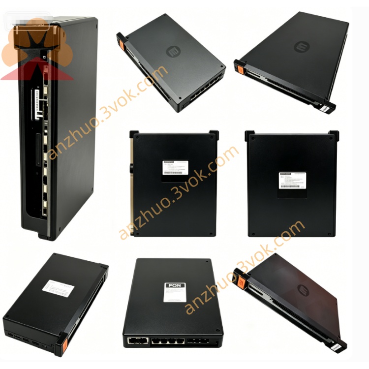
Reliance Electric 57405-C analog I/O drive module
Description
Product Introduction
Model Interpretation
57405-C: Base model; C denotes hardware revision C with enhanced circuit stability and signal accuracy.
0-57405-C: Full AutoMax part number (leading 0 = standard I/O module).
57405: Product family = AutoMax Analog I/O Drive Module.
-C: Revision with improved noise immunity, higher precision, and backward compatibility with earlier revisions.
Technical Parameters
Signal Types: Analog voltage/current input and output.
Input Ranges: 0–10 VDC, 0–20 mA, ±10 VDC.
Output Ranges: 0–10 VDC, 0–20 mA.
Precision: ±0.1% full scale.
Backplane Power: +5 VDC, ~600 mA.
Isolation: 1500 VAC (field-to-logic).
Operating Temperature: 0 °C to +55 °C.
Humidity: 5%–95% non-condensing.
Weight: ~1.4 kg (3 lb).
MTBF: >100,000 hours.
Interface and Communication Configuration
Backplane Interface: Edge connector for AutoMax dedicated backplane bus; provides power and data exchange with CPU.
Field Interface:
TO PMI: 25-pin D-sub for connection to the Process Management Interface (PMI).
Terminal Block: Screw terminals for analog I/O wiring and grounding.
Onboard Indicators: LED for overspeed calibration status and module health.
Configuration: Basic setup via front-panel DIP switches; programmable via AutoMax software for signal scaling and calibration.
Core Functions
Converts analog sensor signals (voltage/current) into digital data for the PLC/DCS.
Outputs analog control signals to actuators, valves, and variable-speed drives.
Provides high-precision signal conditioning and isolation for noise rejection.
Supports real-time data exchange with the AutoMax CPU for closed-loop control.
Facilitates system expansion in process control and factory automation applications.
Application Scenarios
Legacy AutoMax DCS/PLC maintenance in process industries (chemical, power, water treatment).
Precision analog signal interfacing for sensors (temperature, pressure, flow) and actuators.
Factory automation lines requiring closed-loop control with analog devices.
Integration of AutoMax systems with third-party analog instruments and drives.
Operation and Maintenance Instructions
Installation: Power off the rack before insertion; align and seat firmly, tighten mounting screws.
Wiring: Use shielded twisted-pair cables for analog signals; separate from high-voltage lines to avoid EMI.
ESD Protection: Use anti-static wristband/mat when handling; static may damage sensitive circuits.
Routine Maintenance: Quarterly inspection of cables/connectors for wear/corrosion; keep vents clean and dust-free.
Troubleshooting: Check LED status and DIP switch settings; verify signal wiring and calibration before module replacement.
Replacement: Replace entire module if internal fault; do not repair PCB.
Get a Quote