
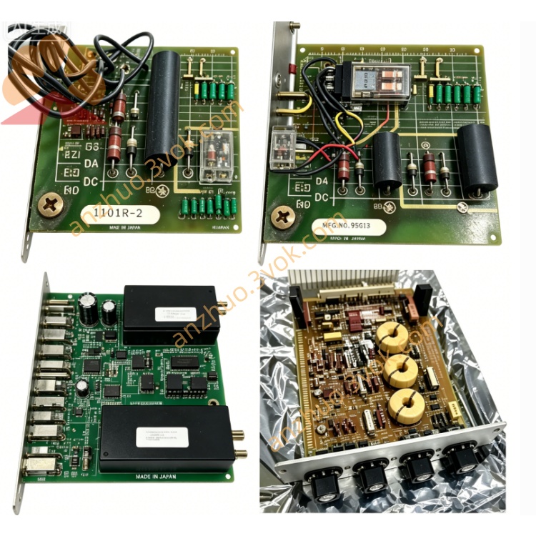
Reliance Electric 57406-E dedicated drive controller module
Reliance Electric 57406-E, also marked as 0-57406-E, is a dedicated drive controller module designed for the AutoMax PLC and DCS system. It undertakes comprehensive control, signal coordination and fault management for motor drive units, and works stably with related power modules. This product has been phased out by the original manufacturer. Currently only refurbished, surplus and used units are available for maintenance and replacement of legacy industrial control systems.
Description
Product Introduction
Reliance Electric 57406-E, also marked as 0-57406-E, is a dedicated drive controller module designed for the AutoMax PLC and DCS system. It undertakes comprehensive control, signal coordination and fault management for motor drive units, and works stably with related power modules. This product has been phased out by the original manufacturer. Currently only refurbished, surplus and used units are available for maintenance and replacement of legacy industrial control systems.
Model Interpretation
The full part number is 0-57406-E. The leading digit 0 represents standard functional modules of the AutoMax series. The code 57406 stands for the product category of drive controller module. The suffix E refers to hardware revision E, which adopts upgraded circuit components, optimized control logic and enhanced heat dissipation design. It keeps full backward compatibility with earlier revisions of the same series. This model number is used for product identification, ordering and inventory management.
Technical Parameters
The module is powered by 5 VDC supplied from the rack backplane with a typical working current of 850 milliamperes. It is equipped with a dedicated industrial microprocessor and solidified professional drive control firmware. It features complete fault detection and code display functions, as well as manual reset and mode selection switches. There is 1500 VAC electrical isolation between the field circuit and internal logic circuit. The operating temperature ranges from 0 degrees Celsius to 55 degrees Celsius, and it can operate reliably in the environment with relative humidity between 5 percent and 95 percent without condensation.
Interface and Communication Configuration
The module connects to the system backplane via edge connectors to obtain power and exchange data with the main controller. It is equipped with multiple dedicated parallel ports to connect with power modules and gate drive assemblies for signal transmission. The front panel is fitted with status indicators, fault code display window, mode switch and reset button. All internal data transmission relies on the exclusive backplane bus of AutoMax system, and no independent external general network ports are configured.
Core Functions
It realizes closed-loop control of motor speed, torque and operating status for various AC and DC drives. It generates and distributes control signals to power units, and ensures synchronous operation of multiple drive devices. It monitors the running state of the whole drive system in real time, records and displays fault information to assist on-site troubleshooting. It supports parameter configuration, function testing and equipment calibration through physical switches and upper computer software.
Application Scenarios
It is mainly applied to the maintenance and part replacement of old AutoMax PLC and DCS equipment. It is widely used in metallurgy, papermaking, power industry and large material handling production lines that require multi-drive coordinated operation. It is suitable for occasions needing high-stability motor drive control, and serves for daily repair and partial renovation of legacy automation projects.
Operation and Maintenance Instructions
Cut off the total power supply of the equipment rack before installation, removal and wiring work. This module is sensitive to static electricity, so standard anti-static protection measures must be taken during handling. Insert the module into the specified slot, make sure the connectors are fully connected, and fasten the fixing screws tightly. Use shielded cables for signal connection, and keep signal lines away from high-voltage circuits to avoid electromagnetic interference. Regularly check cables and connectors for looseness, aging and corrosion, and keep the module surface clean and well ventilated. When abnormal operation or fault alarms occur, check switch settings, displayed fault codes and wiring conditions first. Replace the whole module directly if internal circuit failure cannot be eliminated, and do not disassemble or repair the circuit board privately.
Get a Quote