
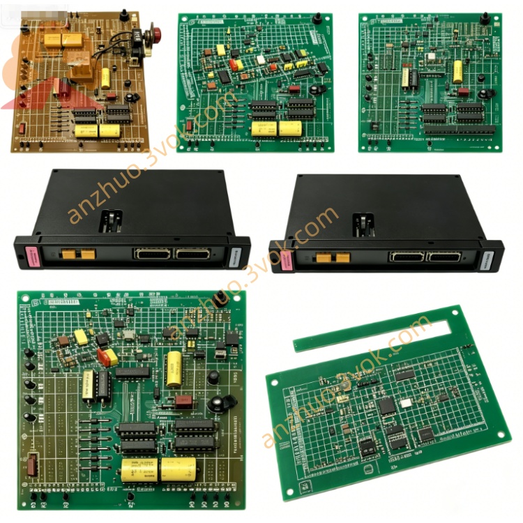
Reliance Electric 57407‑2 (0‑57407‑2) DCS 5000 Processor Module
Reliance Electric 57407-2, also referred to as 0-57407-2, is a central processor module designed for AutoMax PLC and DCS systems. It acts as the main control unit to run user programs and coordinate the operation of all functional modules within the system. This module needs to work with the matching power supply model 57C493, and different types of processors cannot be mixed for use. The product has been discontinued by the original manufacturer, and only refurbished, surplus and used units are available for the maintenance and replacement of legacy industrial control equipment.
Description
Product Introduction
Reliance Electric 57407-2, also referred to as 0-57407-2, is a central processor module designed for AutoMax PLC and DCS systems. It acts as the main control unit to run user programs and coordinate the operation of all functional modules within the system. This module needs to work with the matching power supply model 57C493, and different types of processors cannot be mixed for use. The product has been discontinued by the original manufacturer, and only refurbished, surplus and used units are available for the maintenance and replacement of legacy industrial control equipment.
Model Interpretation
The complete part number is 0-57407-2. The leading digit 0 represents standard functional modules of the AutoMax series. The code 57407 stands for DCS 5000 processor module. The suffix 2 indicates hardware revision 2, which adopts optimized firmware and enhanced fault processing capability, and maintains full backward compatibility with earlier versions of the same series. This model number is used for product identification, ordering and inventory management.
Technical Parameters
The module is powered by 5 VDC supplied from the rack backplane with a typical operating current of 800 milliamperes. It is equipped with a 16-bit central processing unit and runs dedicated real-time operating system. The module is configured with 64 kilobytes parity-enabled RAM and 32 kilobytes ROM. There is 1500 VAC electrical isolation between the internal circuit and external field circuit. The operating temperature ranges from 0 degrees Celsius to 55 degrees Celsius, and it can operate stably in an environment with relative humidity between 5 percent and 95 percent without condensation. It is applicable to 6-slot, 10-slot and 16-slot standard AutoMax racks equipped with cooling fans.
Interface and Communication Configuration
The module connects to the dedicated backplane bus through edge connectors to obtain power and exchange data with other modules. It is built with two independent RS-232 communication ports. One port is used for program uploading, downloading and equipment debugging with professional programming software, and the other port realizes data interaction with human-machine interfaces, monitoring systems and other processors. The front panel is fitted with operation status indicator light, fault code display buttons and manual reset button. The module does not have additional independent network interfaces, and all internal data transmission relies on the system backplane.
Core Functions
It executes various control programs including ladder logic and basic language programs to complete process control and motion control tasks. It uniformly manages all I/O modules, drive modules and communication modules in the system to ensure overall coordinated operation. It conducts real-time monitoring on system operating status, records and displays fault information to support on-site troubleshooting. It supports synchronous operation of multiple processors and provides functions such as online programming, offline debugging and remote diagnosis.
Application Scenarios
It is mainly used as replacement spare parts for maintaining old AutoMax PLC and DCS systems. It is widely applied in metallurgy, papermaking, electric power, material handling and other industrial fields. It is suitable for large-scale automated production lines and multi-drive coordinated control systems, and serves for daily maintenance and partial renovation of legacy automation projects.
Operation and Maintenance Instructions
Cut off the total power supply of the equipment rack before installation, removal and wiring operations. This module is sensitive to static electricity, so complete anti-static protection measures must be taken during handling. Insert the module into the designated slot and ensure the connectors are fully connected, then fasten the fixing screws. Use shielded cables for communication wiring and keep signal lines away from high-voltage circuits to prevent electromagnetic interference. Regularly check cables and connectors for looseness, aging and corrosion, and keep the module surface and ventilation area clean. When abnormal operation or fault alarms occur, check the status indicator and fault codes first. Replace the whole module directly if internal circuit failure cannot be eliminated, and do not disassemble or repair the circuit board privately.
Get a Quote