
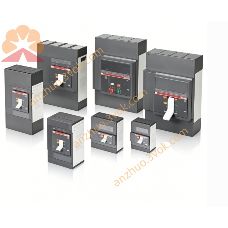
ABB 1SAP250100R0001 (model designation AX521) analog input/output module
ABB 1SAP250100R0001, also named AX521, is an analog input and output module of S500 I/O system for ABB AC500 series PLC. It is equipped with four analog input channels and four analog output channels, and supports multiple signal forms including voltage, current and RTD signals such as Pt100 and Pt1000. This module is developed for industrial automation applications that require high precision signal collection and control output. It features compact structure, simple installation and strong anti-interference performance, which complies with general industrial standards and can work stably in complex industrial environments.
Description
Product Introduction
ABB 1SAP250100R0001, also named AX521, is an analog input and output module of S500 I/O system for ABB AC500 series PLC. It is equipped with four analog input channels and four analog output channels, and supports multiple signal forms including voltage, current and RTD signals such as Pt100 and Pt1000. This module is developed for industrial automation applications that require high precision signal collection and control output. It features compact structure, simple installation and strong anti-interference performance, which complies with general industrial standards and can work stably in complex industrial environments.
Model Interpretation
1SAP stands for the product series of ABB PLC I/O modules, referring to S500 series I/O products. 2501 represents the module category and functional layout, corresponding to the combined analog input and output module with four input channels and four output channels. 0001 refers to the standard product version and revision. AX521 is the commercial model name of this product. AX indicates analog I/O module, the number 5 means compatibility with AC500 system, and 21 stands for the configuration of four analog inputs and four analog outputs.
Technical Parameters
There are four analog input channels. Each channel can be set to receive voltage signals of ±10V and 0 to 10V, current signals of ±20mA and 4 to 20mA, as well as Pt100 and Pt1000 RTD signals. It has four analog output channels, which can output voltage signals of ±10V and 0 to 10V, and current signals of ±20mA and 4 to 20mA. Both input and output channels adopt 13 bit resolution including one sign bit. The overall accuracy reaches ±0.1% full scale under the ambient temperature of 25 degrees Celsius. The sampling rate of analog input channels is 100 samples per second. Isolation design is adopted between channels, and the module can withstand 500V AC voltage for one minute. The working power is 24V DC with a tolerance range of ±10%, and the power consumption is no more than 50mA. The operating temperature ranges from 0 degrees Celsius to 55 degrees Celsius, and the storage temperature ranges from minus 40 degrees Celsius to 70 degrees Celsius. The applicable relative humidity is between 5% and 95% without condensation. The protection level of the module shell is IP20. It is installed on standard 35mm DIN rail, with external dimensions of 62mm in depth, 67.5mm in width and 76mm in height, and the total weight is 0.129kg.
Interface and Communication Configuration
The field signal interface adopts screw terminal blocks, which supports two wire and three wire connection modes, and each channel is marked clearly for convenient wiring. The module connects to the PLC through the built in backplane bus interface, realizing high speed data transmission with the controller, and no extra communication modules are needed to complete basic I/O functions. It can work with main industrial protocols such as PROFIBUS DP, CANopen and Modbus RTU by matching the extended communication ports of the PLC host, so as to access different industrial control networks. The device is fitted with multiple LED indicators to display power status, module running status and channel working conditions in real time.
Core Functions
It can collect various analog signals from on site sensors including temperature, pressure, flow and liquid level, and convert analog signals into digital data for PLC processing. The module converts digital control commands sent by the PLC into standard analog signals to drive field actuators like regulating valves and frequency converters. Users can independently set signal type, signal range and filter parameters for each input and output channel through software to adapt to different field equipment. Channel isolation design effectively reduces external electromagnetic interference and guarantees stable operation. The module has built in fault detection functions, which can identify channel open circuit, short circuit and signal over range problems, and upload fault information to the control system for quick troubleshooting. The high sampling rate ensures the real time collection and rapid response of dynamic process signals.
Application Scenarios
It is widely used in process control industries including petroleum, chemical engineering, pharmaceutical production and water treatment, to monitor and adjust temperature, pressure, flow and liquid level parameters of production equipment. It is applicable to heating, ventilation and air conditioning systems in building automation for temperature and humidity monitoring and control. It can be deployed in power plants and new energy projects to complete signal collection and equipment control in energy management systems. In machinery manufacturing industry, it matches processing machine tools, packaging equipment and assembly lines to realize precision drive and signal collection. It also serves food and beverage production lines to control temperature, pressure and flow parameters and maintain stable production conditions.
Operation and Maintenance Instructions
Install the module on standard 35mm DIN rail inside industrial control cabinet. Keep sufficient ventilation space around the device for heat dissipation, and do not install it in places with direct sunlight, high humidity or corrosive gas. Use shielded cables for analog signal wiring, and separate signal cables from power cables to avoid interference. Connect lines according to terminal markings, and control the tightening torque of terminal screws between 0.5Nm and 0.6Nm. Complete channel parameter configuration via supporting programming software, download the configuration program to the PLC, and confirm the normal running state through indicator lights. Conduct regular inspection in daily use, check the firmness of wiring and the cleanliness of terminals regularly. Wipe the surface of the module with dry cloth when cleaning, and do not use liquid cleaning agents. If the power indicator is off, check the 24V DC power supply and related lines. If the running indicator flashes abnormally, re download the configuration program. When the channel indicator gives an alarm, check wiring and field equipment to eliminate open circuit, short circuit or signal over range faults. Cut off the system power supply before replacing the module, disconnect all connecting lines, take down the old module and install the new one, then reconnect lines and complete parameter configuration. Keep the module in dry and cool environment with original package during storage, and avoid severe vibration and collision in transportation. Follow official service regulations for after sales support when equipment failure occurs.
Get a Quote